background image

Questions? Call Toll Free at 1-800-737-2112


Copyright © 2009 MAT Engine Technologies, LLC

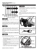
How to Prepare for Storage

D

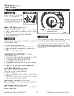
Never store the tiller indoors with fuel in the fuel tank.  Never store in an enclosed, poorly ventilated area where fumes 

could reach an open flame, a spark or a pilot light as on a furnace, water heater or clothes dryer.  Allow engine to cool 

before storing unit.

Do not remove gasoline while inside a building, near a fire, or while you smoke.  Gasoline fumes can cause an explosion 

or a fire.

NOTE:

 A yearly checkup or tune-up at an authorized service center will make sure that the tiller will provide maximum per-

formance for the next season.
When the tiller is put in storage for thirty days or more, the following steps should be followed to make sure the tiller is in good 

condition the next season.

1. Let the engine run until it is out of gasoline.

2. Change the oil by following 

instructions under “How to Change the Oil.”

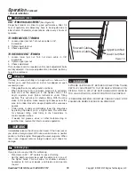
3. Remove the spark plug from the cylinder. Pour one ounce of oil into the cylinder. Slowly pull the recoil-start grip so  

  that the oil will protect the cylinder. Install a new spark plug in the cylinder.  Pull starter handle slowly a few times to  

  distribute oil. Pull recoil slowly until resistance is felt.  This will close the cylinder valves.

DO NOT attach spark plug wire to spark plug when storing unit.
4. Clean tiller.  Remove all dirt, leaves, debris, grease, etc. from the tiller - including cylinder cooling fans, recoil starter  

  cover holes, under fuel tank, and under muffler.  

5. Check the tiller for worn or damaged parts. Have damaged parts replaced if necessary.


6. Tighten any loose hardware.

7. Apply lubrication as directed in Maintenance section.

8. Put the unit in a building that has good ventilation.

9. Cover the tiller with a breathing material.

Maintenance 

(Continued)

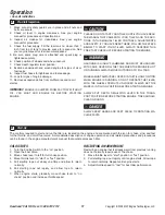
• Save all instructions 

You  may  have  further  questions  about  assembling,  operating,  or  maintaining  this  TILLER.  If  so,  you  can  contact  our 

Technical Service Department at 1-800-737-2112 (English only). 

You may also write to:

METL Corporate Office - CORRESPONDENCE ONLY

ATTN: Technical Service – METL

6700 Wildlife Way

Long Grove, IL 60047

Technical Service

When contacting the Technical Service Department, have ready:

• Your Name

• Your Address

• Your Phone Number

• Model Number of Product

• Date of Purchase (include copy of receipt for written requests)

If you need assistance or have any questions, CALL 

TOLL FREE: 1-800-737-2112.

WARNING

WARNING

WARNING


19


Содержание P-RTT-196MD

Страница 1: ...nd maintaining your Tiller Read and save these instructions Refer to this manual each time before using your Tiller Record the following for future reference Mfg Date Code _______________________ Date of Purchase Attach a copy of your sales receipt Consumer Toll Free Number 1 800 737 2112 Refer to the website for electronic manual and parts book www gardnerinc com KEEP THIS MANUAL FOR FUTURE REFER...

Страница 2: ...haust contains carbon monoxide an odorless and deadly gas NEVER run unit indoors or in a poorly ventilated area Do not use if children or bystanders are present Do NOT touch hot muffler or cylinder These parts are extremely hot from operation and may remain hot for a short time after operation Rotating tines can cause serious injury Keep hands feet and clothing away To reduce risk of fire clean sp...

Страница 3: ...g or making repairs always disconnect spark plug wire and put wire where it cannot contact the spark plug PREPARATION SAFETY WARNING Read understand and follow all instructions on the machine and in this manual Be thoroughly familiar with the controls and the proper use of the tiller before starting Know how to stop the engine quickly Familiarize yourself with all the safety and operating decals o...

Страница 4: ...m the spark plug Watch for holes ruts bumps or other rough ground Tall grass can hide obstacles Always look behind and down and use caution when using reverse or pulling the tiller towards you Never attempt to start the tiller unless both wheels are in the locked position This acts as a brake for the tiller Always start the tiller on the level surface WARNING Disengage clutch lever and stop engine...

Страница 5: ... when specifically recommended by the manufacturer Keep the tiller in safe working condition Check all fasteners at frequent intervals for proper tightness When servicing or repairing the tiller do not tip the machine over or up unless specifically instructed to do so in this manual Service and repair procedures can be done with the tiller in an upright position Some procedures will be easier if t...

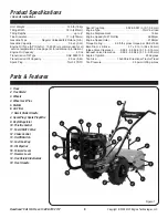
Страница 6: ...ins 5 Muffler 6 Air Filter 7 Recoil Starter Handle 8 Spark Plug Spark Plug Wire 9 Depth Regulator 10 Throttle Control 11 Fuel ON OFF Valve 12 Choke Control 13 On Off Switch 14 Fuel Tank Cap 15 Oil Dipstick 16 Forward Lever 17 Reverse Lever 18 Tine Shield Side Guards 19 Front Handle Spark Plug Gap 0 028 0 031 in 0 7 0 8 mm Engine Type OHV 4 stroke Engine Displacement 196cc Engine Speed Full Throttl...

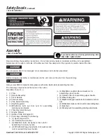
Страница 7: ...afety labels are illustrated below and are shown here to help familiarize you with the location and content to the safety messages you will see as you perform normal tilling operations Please review these labels now If you have any questions regarding their meaning or how to comply with these instructions reread the complete safety instruction text on the preceding pages or contact your local deal...

Страница 8: ...lds while assembling the tiller The following components will be found in the carton Quantities shown in 1 1 Tiller 2 1 Handle Assembly 3 1 Front Handle 4 2 Tine Assembly 5 1 Tine Guard Assembly 6 1 Depth Regulator 7 2 M10x50mm bolts and lock nuts for assembling stationary side shields 8 1 Tiller Operator s Manual 9 1 Engine Manual 10 1 Bottle of SAE 30 Engine Oil 11 1 Parts bag containing the fol...

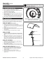
Страница 9: ... tire thread facing the direction as shown 3 Slide the wheel hub onto the wheel axle 4 Align the wheel hub hole with the hole in the axle and insert the locking pin 5 Rotate the locking pin ring to lock the pin in position INSTALL THE TINES 1 Check the orientation of the tine blade The sharp cutting edge should be facing the direction of tine rotation for your tiller 2 Install the tine assemblies ...

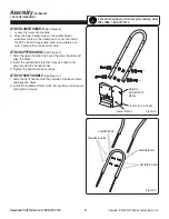
Страница 10: ...bolts lock washers and nuts Tighten all four bolts at this time ATTACH UPPER HANDLE See Figure 5 1 Slide the upper handle down over the lower handle and align the holes 2 Insert the saddle bolts into the holes as shown and securely with the handle knobs 3 Tighten the handle knobs securely ATTACH FRONT HANDLE See Figure 1 1 Slide the front handle onto the outside of the base frame and align the hol...

Страница 11: ...il Fill Cap Dipstick Fuel Tank Cap Oil Fill Cap Dipstick Upper Limit Lower Limit Figure 6 Figure 7 Engine shipped without oil Failure to add oil will result in serious engine damage A bottle of SAE 30 engine oil is included with your tiller Refer to the chart on the right for alternative oil types to use at different temperatures Always use a high quality detergent oil classified For Service SG SH...

Страница 12: ...ed with care Never fillthe tank when the engine is hot or running Always move outdoors to fill tank Wheels mustalways be locked in the tilling position when engine is running Do not operate the tiller with the wheel lockouts unlocked Always set the wheels in tilling position before starting engine Always put depth regulator lever in the trans port position before starting engine Tines should clear...

Страница 13: ...by putting slight downward pressure on the handlebars You can stop the tiller by releasing the drive safety control levers to the neutral position CAUTION ALWAYS PRESS THE FORWARD OR REVERSE DRIVE LAVERS DOWN COMPLETELY ONTO THE HANDLE BAR GRIPS FAILURE TO DO SO MAY RESULT IN EXCESSIVE DRIVE BELT WEAR AND PRE MATURE DRIVE BELT FAILURE WARNING Temperature of muffler and near by areas may ex ceed 15...

Страница 14: ... and operating instructions are given on page 11 Please read this section and all operat ing and safety instructions before starting your tiller As a safety precaution the drive safety control levers will not lock in the forward or reverse position WARNING DO NOT FIX THE FORWARD OR REVERSE DRIVE LEVERS IN DRIVE POSITION BY ANY OTHER MEANS THAN MANUALLY USING YOUR RIGHT HAND DO NOT TIe OR OTHERWISE...

Страница 15: ...3 Align handlebar to desired holes on the lower handlebar mount 4 Install bolts and nuts Retighten all four bolts securely DEPTH REGULATOR LEVER See Figure 3 Tilling depth is controlled by the height of the depth regulator lever To adjust tilling depth 1 Remove detent pin 2 Raise the depth regulator lever to position tines at chosen tilling depth 3 Align hole in depth regulator lever with hole in ...

Страница 16: ... lever follow instructions under Tilling section This will allow for shallow tilling With the drag stake in this position make several light passes over the area to be tilled Reset for deeper depths with successive passes If tiller jumps or skids uncontrollably lower the drag stake by placing the detent pin in a higher hole This will allow for shallower tilling Hold firmly to the handlebars to con...

Страница 17: ...ge oil every 25 hours if operating under heavy load or in high temperatures 4 Clean air filter every 10 hours if operating under dusty conditions Use only GENUINE replacement parts Other parts may damage the unit or result in injury CAUTION Service Records Fill in dates as you complete regular service Before Each Use After Every 10 Hours of Use After Every 25 Hours of Use After Every 50 Hours of U...

Страница 18: ...tall the reverse drive belt a Insert the belt from underneath the unit and up around the reverse belt idler b Place the lower loop of the belt around the forward portion of the transmission pulley c Replace the reverse belt idler into the reverse belt idler bracket The belt should not go around the engine pulley Be sure the belt is inside of the reverse belt guide studs 9 Tighten the forward and r...

Страница 19: ...unt of oil When replacing oil the tiller transmission holds 18 22ounces Do not overfill Check the oil level annually To check the oil level 1 Move tiller to level ground 2 Remove oil level dipstick located between the handlebar mounts on the engine mount If the oil level couldn t touch the dipstick fill the oil to recommended level 3 Replace oil level dipstick in the filler hole 4 Note that the dr...

Страница 20: ...plug in the cylinder Pull starter handle slowly a few times to distribute oil Pull recoil slowly until resistance is felt This will close the cylinder valves DO NOT attach spark plug wire to spark plug when storing unit 4 Clean tiller Remove all dirt leaves debris grease etc from the tiller including cylinder cooling fans recoil starter cover holes under fuel tank and under muffler 5 Check the til...

Страница 21: ...e and clean air filter 5 Remove fuel filter Inspect Replace if necessary 6 Drain fuel tank Clean fuel tank Fill with fresh fuel 7 Take unit to an authorized service center for Carburetor adjustment Excessive vibration noise 1 Loose parts 2 Engine problems above 3 Abnormal noise or squeal coming from belt drive 1 Tighten all fasteners 2 Refer to engine solutions above 3 Normally due to belt pulley ...

Страница 22: ...e accident lack of proper maintenance tampering or alteration Travel handling transportation and incidental costs associated with warranty repairs are not reimbursable under this warranty and are the responsibility of the owner To the full extent allowed by the law of the jurisdiction that governs the sale of the product this express warranty excludes any and all other expressed warranties and lim...

Страница 23: ...ed below provided there has been no abuse neglect or improper maintenance of your power equipment engine Where a warrantable condition exists METL will repair your power equipment engine at no cost to you including diagnosis parts and labor The emissions control system is warranted for two years If any emissions related part on your engine is defective the part will be repaired or replaced by METL...

Страница 24: ...repair of your engine or product may be disallowed METL shall not be held liable hereunder for failures of any warranted parts caused by the use of such an unapproved add on modified counterfeit and or gray market part You must take your power equipment engine or the product on which it is installed along with evidence of the date of the sale to the original purchaser at your expense to any METL A...

Страница 25: ...l Exhaust System Catalytic muffler assembly if so equipped muffler gasket ex haust manifold Crankcase Breather Assembly Breather connection tube Miscellaneous Parts Used in Above Systems Hoses belts connectors and assemblies Evaporative Emissions Components Fuel line fuel line fittings clamps fuel tank carbon canister can ister mounting brackets carburetor purge port connector 1 Covered up to the ...

Страница 26: ......

Страница 27: ...1 800 737 2112 Este producto contiene una o más substancias químicas que consta al Estado de California producen cáncer y malformaciones congénitas u otros daños reproductivos Lavarse las manos después de manipularlo ADVERTENCIA IMPORTANTE Gracias por comprar esta motocultivadora Powermate Este manual brinda instrucciones completas para la operación y mantenimiento seguros de la motocultivadora Le...

Страница 28: ...or contienen monóxido de carbono un gas inodoro y letal JAMÁS hacer funcionar la unidad en espacios interiores o en áreas con ventilación deficiente No utilizar la motocultivadora ante la presencia de niños o circunstantes NO tocar el silenciador ni el cilindro calientes Estas piezas están sumamente calientes debido al funcionamiento y podrían permanecer calientes durante un período de tiempo cort...

Страница 29: ...a SEGURIDAD DURANTE LA PREPARACIÓN ADVERTENCIA Leer entender y seguir todas las instrucciones en la máquina y en este manual Familiarizarse completamente con los controles y el uso apropiado de la motocultivadora antes del arranque Sépase cómo parar el motor rápidamente Familiarizarse con todos los marbetes de seguridad y funcionamiento en este equipo ADVERTENCIA Inspeccionar completamente el área...

Страница 30: ...dora a menos que ambas ruedas estén en la posición inmovilizada Esto actúa como un freno para la motocultivadora Siempre arrancar la motocultivadora en una superficie a nivel ADVERTENCIA Desenganchar la palanca del embrague y parar el motor antes de dejar la motocultivadora en la posición de operación Esperar hasta que las azadas paren completamente antes de retirar despojos o efectuar cualquier a...

Страница 31: ...ora en condiciones de funcionamiento seguro Revisar todos los sujetadores a intervalos frecuentes para una sujeción adecuada Al dar mantenimiento a la motocultivadora o repararla no inclinar la máquina lateral o longitudinalmente a menos que así lo instruya este Manual específicamente Los procedimientos de mantenimiento y reparación se pueden efectuar con la motocultivadora en la posición vertical...

Страница 32: ...adura del arrancador de retroceso 8 Bujía Cable de bujía 9 Regulador de profundidad 10 Control del regulador 11 Válvula de ALIMENTACIÓN CORTE de combustible 12 Control del estrangulador 13 Interruptor de encendido apagado On Off 14 Tapa del tanque de combustible 15 Varilla medidora del nivel de aceite 16 Palanca de avance 17 Palanca de retroceso 18 Protectores laterales de azadas 19 Asidero fronta...

Страница 33: ...n y se muestran aquí para ayudar a familiarizarse con la ubicación y contenido de los mensajes de seguridad que el operador verá durante las operaciones normales de labranza Revísense estos marbetes ahora mismo Si se tiene alguna pregunta con respecto a su significado o a cómo cumplir estas instrucciones leer nuevamente el texto completo de la instruc ción de seguridad en las páginas que anteceden...

Страница 34: ...SI La caja contiene los componentes siguientes Cantidades mostradas en 1 1 Motocultivadora 2 1 Asidero 3 1 Asidero frontal 4 2 Tren de azadas 5 1 Protector de azadas 6 1 Regulador de profundidad 7 2 Pernos y contratuercas M10 x 50 mm para montaje de los resguardos laterales estacionarios 8 1 Manual de operación de la motocultivadora 9 1 Manual del motor 10 1 Envase de aceite de motor SAE 30 11 1 B...

Страница 35: ...n mostrada 3 Deslizar el cubo de la rueda sobre el eje de las ruedas 4 Alinear el agujero del cubo de la rueda con el agujero en el eje e insertar el pasador de seguridad 5 Girar el aro del pasador de seguridad para asegurar el pasador en posición INSTALAR LAS AZADAS 1 Verificar la orientación de la hoja de las azadas El borde cortante afilado debe estar orientado en dirección a la rotación de las...

Страница 36: ...ercas Apretar los cuatro pernos en este paso INSTALAR EL ASIDERO SUPERIOR véase la figura 5 1 Deslizar el asidero superior sobre el asidero inferior y alinear los agujeros 2 Insertar los pernos curvos en los agujeros como se muestra y asegurarlos con las perillas del asidero 3 Apretar las perillas ajustadamente INSTALAR EL ASIDERO FRONTAL véase la figura 1 1 Deslizar el asidero frontal sobre el ex...

Страница 37: ...apa de llenado va rilla medidora del nivel de aceite Límite superior Límite inferior Figura 6 Figura 7 CUIDADO El motor se envía sin aceite El no agregar aceite causará daños severos al motor Se incluye un envase de aceite de motor SAE 30 con la motocultivadora Consultar el gráfico a la derecha para obtener información sobre tipos alternativos de aceite a usarse a diferentes temperaturas Siempre u...

Страница 38: ...marcha Siem pre llenar el tanque en espacios exteriores Es preciso que las ruedas estén siempre asegu radas en la posición de labranza cuando el motor esté en marcha No operar la motocultivadora con los seguros de las ruedas no instalados Siempre fijar las ruedas en la posición de labranza antes de arrancar el motor Siempre colocar la palanca del regulador de pro fundidad en la posición para trans...

Страница 39: ...de la motocultivadora en cualquier momento mediante presión leve descendente sobre las barras del asidero Se puede parar la motocultivadora al soltar las palancas de control motriz seguro a la posición neutra CUIDADO SIEMPRE OPRIMIR LAS PALANCAS DE MARCHA DE AVANCE O RETROCESO COMPLETAMENTE CONTRA LOS ASIDEROS DE LAS BARRAS DEL ASIDERO NO HACERLO PODRÍA CAUSAR DESGASTE EXCESIVO DE LA CORREA DE IMP...

Страница 40: ...ón y todas las instrucciones sobre operación y seguridad an tes de arrancar la motocultivadora Como precaución de seguridad las palancas de control motriz seguro no se enganchan ni en la posición de avance ni en la de retroceso ADVERTENCIA NO FIJAR LAS PALANCAS DE MARCHA DE AVANCE O DE RET ROCESO EN LA POSICIÓN DE IMPULSIÓN POR NINGÚN OTRO MEDIO QUE LA MANO DERECHA DEL OPERADOR NO ATAR NI ASEGURAR...

Страница 41: ...barra del asidero inferior 4 Instalar los pernos y las tuercas Apretar de nuevo y ajustadamente los cuatro pernos ADVERTENCIA El motor debe estar apaga do antes de ajustarse cual quier control Se debe tener sumo cuidado al operarse la motocultiva dora en retroceso Wheel lock pin in free wheel position axle holes only FRONT Figura 11 ADVERTENCIA No ajustar la profundidad de labranza a menos que las...

Страница 42: ...arvariaspasadas livianas sobre el área a labrarse Cambiar la configuración para mayores profundidades en pasadas sucesivas Si la motocultivadora salta o patina incontrolablemente bajar la estaca de arrastre mediante la colocación del pasador de detención en un agujero más alto Esto dará lugar a una labranza menos profunda Sujetar las barras del asidero firmemente para controlar sacudidas repentina...

Страница 43: ...sado o en altas temperaturas 4 Limpiar el filtro de aire cada 10 horas si se está operando bajo condiciones pulvígenas ADVERTENCIA Utilizar sólo piezas de repuesto GENUINAS Otras piezas podrían dañar la unidad o causar lesiones Registros de servicio Anotar las fechas a medida que se lleve a cabo el servicio normal Antes de cada uso Después de cada 10 horas de uso Después de cada 25 horas de uso De...

Страница 44: ...tirar los resguardos superior e inferior de la correa 5 Para retirar la correa motriz de retroceso a Retirar la polea guía de la correa de retroceso b Deslizar la correa para librarla de las guías de la correa de retroceso y de la polea del motor c Tirar de la correa hacia abajo y alejarla de la polea de transmisión 6 Para retirar la correa motriz de avance a Retirar los dos prisioneros guía de la...

Страница 45: ...la motocultivadora acepta de 18 a 22 onzas fluidas No sobrellenarla Revisar el nivel del aceite anualmente Para revisar el nivel del aceite 1 Mover la motocultivadora a una superficie a nivel 2 Retirar la varilla medidora del nivel de aceite ubicada entre los soportes de montaje de las barras del asidero en el soporte del motor Si el nivel de aceite no entra en contacto con la varilla medidora lle...

Страница 46: ...rancador lentamente unas cuantas veces para distribuir el aceite Tirar del arrancador de retroceso hasta sentirse resistencia Esto cierra las válvulas del cilindro ADVERTENCIA NO conectar el cable de la bujía a ésta al almacenarse la unidad 4 Limpiar la motocultivadora Retirar toda mugre hojas residuos grasa etc de la motocultivadora incluidos los ventiladores de enfriamiento del cilindro los aguj...

Страница 47: ... aire 5 Retirar el filtro de combustible Inspeccionarlo Reemplazarlo si fuera necesario 6 Drenar el tanque de combustible Limpiar el tanque de combustible Llenarlo con combustible fresco 7 Llevar la unidad a un centro de servicio autorizado para ajuste del carburador Vibración o ruido excesivo 1 Piezas flojas 2 Problemas del motor arriba 3 Ruido anormal o chirrido procedente de la correa 1 Apretar...

Страница 48: ...do accidente falta de mantenimiento apropiado manipulación imprudente y peligrosa o alteración Los costos de viaje manipulación transporte e incidentales asociados con reparaciones bajo garantía no son reembolsables bajo esta garantía y son responsabilidad del propietario Hasta donde lo permita la ley de la jurisdicción que gobierne la venta de este producto esta garantía expresa excluye cualesqui...

Страница 49: ... que figuran a continuación siempre y cuando no haya habido uso indebido descuido o mantenimiento inadecuado del motor para equipo mecánico Cuando exista una condición garantizable METL reparará el motor para equipo mecánico sin costo alguno para el propietario incluyendo el diagnóstico las piezas y la mano de obra El sistema de control de emisiones contaminantes está garantizado durante dos años ...

Страница 50: ...la Garantía del sistema pro control de emisiones contaminantes la reclamación para reparación del motor o producto podría declararse nula y sin efecto METL no asumirá responsabilidad alguna bajo la presente garantía por fallos de toda pieza garantizada causados por el uso de dicha pieza no aprobada adicional modi ficada falsificada y o del mercado gris El propietario ha de llevar el motor para equ...

Страница 51: ...provisto empaque del silenciador múltiple de escape Unidad del respirador del cárter del cigüeñal Tubo de conexión de respirador Piezas misceláneas utilizadas en los sistemas anteriores Mangueras fajas conectores y montajes Componentes de emisiones contaminantes evaporativas Tubería para combustible accesorios de tubería para combus tible abrazaderas tanque de combustible soportes para montaje de ...

Страница 52: ......

Отзывы: