background image

  12  

Configuring the PowerLeap™ PL-iP3


PowerLeap

 Installation Guide


• 

For 

Celeron users

 please select 1.5V (the default setting), 1.65, 

or

 2.0V. 


1.5V Celeron (FC-PGA): 

JP3

JP4

JP5

JP6

JP7

JP11

1

2

3

5

4

6

Closed Closed

Closed

Closed

Open

Open

Open

Open


1.65V Celeron (FC-PGA): 

JP3

JP4

JP5

JP6

JP7

JP11

1

2

3

5

4

6

Closed Closed Open

Open

Open

Open

Closed

Closed


Note: If your Celeron documentation indicates a V/Core of 1.7V, 
please set the jumpers (as shown above) for 1.65V. This setting will 
not affect your CPU’s health or performance. 

Содержание PL-iP3

Страница 1: ...POWERLEAP PL iP3 Pentium III Celeron CPU Upgrade for Slot 1 242 Contact Slot Connector Systems Version 1 0 ...

Страница 2: ...ProMMX IPS PL 54C MMX PL C6 200 PL OD54C PL 386 and PL 586 are trademarks of PowerLeap Products Inc Intel MMX and Pentium are registered trademarks of Intel Corporation Microsoft Windows Windows NT and MS DOS are either trademarks or registered trademarks of Microsoft Corporation Other product names mentioned herein are used for identification purposes only and may be trademarks and or registered ...

Страница 3: ...tage_____ 4 Locating Pin 1 on your CPU and ZIF Socket ______________________ 5 Determining CPU Performance ________________________________ 5 Configuring the PowerLeap PL iP3 7 Setting Jumper Switches ______________________________________ 7 Selecting Frontside Bus FSB Speed_____________________________ 8 Selecting Voltage___________________________________________ 11 Enabling Multiple Processors ...

Страница 4: ... CPU Heatsink Fan ______________________________ 20 Completing the Installation of the PL iP3________________________ 21 Upgrading Your Computer s BIOS_____________________________ 23 Using the PL iP3 Without the Retention Cartridge _________________ 24 FAQ 27 ...

Страница 5: ...or maximum safety z Includes PowerLeap s unique Redundant Overheating Protection function z When used with SMP compliant Celeron PPGA CPUs provides dual CPU support on dual Slot 1 motherboards Not all Intel CPUs are SMP compliant To determine if you have SMP compliant CPUs check the Intel web site you will need to know the stepping of your CPUs z Supports multiple voltage settings for V Core 1 5V ...

Страница 6: ...FC PGA and PPGA Form Factors The FC PGA Flip Chip Pin Grid Array form factor is a chip packaging designed for Intel Pentium III Coppermine processors and newer Celeron CPUs On the FC PGA package the processor s silicon core faces up and is exposed This allows the core to have direct contact with a heatsink fan FC PGA PPGA Intel Celeron processors are available in the FC PGA and PPGA Plastic Pin Gr...

Страница 7: ...determined from your motherboard documentation by contacting your motherboard manufacturer or by checking the chipset installed on your motherboard In addition to the motherboard s supported frontside bus speed you will need to know the method that the board provides for setting the FSB speed Your motherboard may either provide jumper switches for setting the FSB speed or offer jumperless speed co...

Страница 8: ...ormation concerning your CPU FSB rating and CPU V Core voltage can be found on a black label attached to the face plate of your new Intel processor as shown below If your CPU faceplate does not show information in the manner shown please check your CPU documentation or contact Intel for the information This black label contains a wealth of information about your CPU including clock speed the size ...

Страница 9: ...operly align the joining of the CPU to the ZIF socket Pin3 1 Pin 1 FC PGA Pin 1 PPGA Pin 1 Determining CPU Performance To compare the performance increase provided by the PL III we suggest running the PowerLeap CPU Control Panel both before and after installation If you are uncertain about the speed of your existing CPU you can determine the speed by running the PowerLeap CPU Control Panel The CPU...

Страница 10: ...6 Before You Begin PowerLeap Installation Guide ...

Страница 11: ...wer On LED and Redundant Overheating Protection functions Setting Jumper Switches You can configure operating characteristics of the PL iP3 by setting jumper switches consist of pin headers and plastic connecting caps on the board For convenience the PL iP3 uses jumper caps of different color to specify different functions The jumper switches are shown in the graphic below FSB Jumpers Voltage Jump...

Страница 12: ...ange the jumper settings refer to the following sections of this chapter to understand the jumper functions Selecting Frontside Bus FSB Speed To get the best CPU performance you can use jumper switches on the PowerLeap PL iP3 to set the frontside bus speed The PL iP3 s default FSB speed setting is 66MHz Note Although an incorrect FSB setting will not damage your CPU or your PowerLeap upgrade it ca...

Страница 13: ...he motherboard s FSB setting is set to a specific speed the PL iP3 s speed setting will have no effect be overridden If your motherboard offers jumperless speed configuration through settings in BIOS the PL iP3 s speed setting will have no effect be overridden If your motherboard offers jumperless speed configuration by automatically setting the FSB speed to the FSB rating of the CPU you can use t...

Страница 14: ... FSB speed to the FSB rating of the CPU Otherwise the PL iP3 s FSB speed setting will have no effect the motherboard s FSB speed setting will override the PL iP3 s setting Your choice will also be determined by the supported FSB speed of your motherboard and the FSB rating of the processor 100 or 133MHz Your actual FSB speed and its setting will be based on whichever speed is lower For example if ...

Страница 15: ...e voltage printed on the faceplate of your CPU or as specified in your CPU documentation CAUTION It is imperative that you use the correct jumper setting for the appropriate voltage of your CPU An incorrect setting may cause serious damage to your CPU and or your PL iP3 Please take a moment to verify your CPU s voltage before continuing Voltage Jumpers JP 3 4 5 6 7 JP11 Voltage Jumpers Location Di...

Страница 16: ... JP4 JP5 JP6 JP7 JP11 1 2 3 5 4 6 Closed Closed Closed Closed Open Open Open Open 1 65V Celeron FC PGA JP3 JP4 JP5 JP6 JP7 JP11 1 2 3 5 4 6 Closed Closed Open Open Open Open Closed Closed Note If your Celeron documentation indicates a V Core of 1 7V please set the jumpers as shown above for 1 65V This setting will not affect your CPU s health or performance ...

Страница 17: ...hown above for 1 65V This setting will not affect your CPU s health or performance Enabling Multiple Processors The PL iP3 supports dual processing for SMP enabled Celeron PPGA CPUs Symmetric Multi Processing SMP is a method allowing the use of multiple processors in a single computer system If your computer system does not have slots for multiple CPUs please disregard this section Not all Intel C...

Страница 18: ...e Power on LED Function To ensure the safety of your upgrade components PowerLeap provides the Power On LED function This safety feature enables you to determine whether or not power is flowing through the PL iP3 and helps prevent costly damage to both your expensive CPU and the upgrade board itself Caution Never insert nor remove your CPU from the PL iP3 when the Power On LED is on Inserting or r...

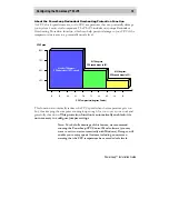
Страница 19: ...rees CPU operates at 100 speed 60 55 CPU Speed 55 At 70 degrees CPU speed drops to 50 At 85 degrees CPU speed drops to 25 This function automatically reduces the CPU speed when the temperature gets too hot thus keeping the computer running long enough for you to save your work and gracefully shut down This protection function is automatically enabled it is not necessary to configure jumper setting...

Страница 20: ...16 Configuring the PowerLeap PL iP3 PowerLeap Installation Guide ...

Страница 21: ...oving the Existing CPU 1 Place your computer where you will have plenty of space to work 2 Turn the computer off and disconnect all power cords and cables from the rear of the computer 3 Remove the cover from the computer as described in the computer documentation 4 Locate your existing CPU on the computer s motherboard 5 Remove the right end of the CPU from the slot ...

Страница 22: ...erLeap PL iP3 PowerLeap Installation Guide 6 Remove the left end of the CPU from the slot 7 Complete removing your existing CPU from the motherboard Installing your CPU into the PL iP3 1 Raise the socket arm on your PL iP3 ...

Страница 23: ...rt your new CPU into the PL iP3 ZIF socket noting the placement of pin 1 3 Lock the CPU into the ZIF socket by pressing the socket arm down completely 4 Determine that there is no space between the newly inserted CPU and the ZIF socket Important No space between CPU and ZIF socket ...

Страница 24: ...heatsink fan upside down and remove the paper backing from the thermal pad When the heatsink fan is installed the thermal pad will adhere to the top of the CPU dissipating heat and protecting the exposed die on FC PGA CPUs 2 Attach the left clip of the heatsink to the tab on the left hand side of the socket ...

Страница 25: ...tsink to the tab on the right hand side of the socket Completing the Installation of the PL iP3 1 Insert your PL iP3 into the 242 contact slot connector on your motherboard 2 Find the connectors for the fan and the external power supply on the PL iP3 Connection for Fan JP9 Connection for Power Supply JP10 ...

Страница 26: ...P9 on the PL iP3 4 Attach the brown connector on the provided power supply cable to the power supply connector JP10 on the PL iP3 Then attach the male connector on the other end of the cable to one of the female connectors from your computer s power supply Installation is complete Enjoy your increased processing power ...

Страница 27: ...nformation about the motherboard chipset manufacturer and BIOS ID string Look for upgrades at the sites of your motherboard s original BIOS manufacturer AMI http www amibios com Award http www award com MR BIOS http www mrbios com and Phoenix http www ptltd com produce popular BIOS software Try a third party BIOS Micro Firmware http www firmware com and Unicore http www unicore com both sell BIOS ...

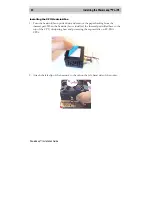
Страница 28: ...iP3 directly into your motherboard s 242 contact slot connector Note The PL iP3 s retention cartridge is designed for use with the S E C C RM and the Universal RM If your motherboard came with either of these types of retention mechanisms you do not need to remove the PL iP3 from the retention cartridge Removing the PL iP3 from the Retention Cartridge 1 Pull the side arms left and right of the car...

Страница 29: ... 3 Free the PL iP3 from the retention cartridge by putting your index fingers behind the corners of the PL iP3 and firmly pushing on the back posts with your thumbs as you pull the PL iP3 toward you with your fingers 4 Lift the PL iP3 out of the retention cartridge ...

Страница 30: ...26 Installing the PowerLeap PL iP3 PowerLeap Installation Guide ...

Страница 31: ...tely displays a Warning message on screen If the temperature continues to climb this function repeats itself to gradually reduce the CPU speed thus keeping the computer running long enough for you to save your data and gracefully shut down Why does Intel lock the clock multipliers on their CPUs Locking the multiplier helps to prevent remarking of CPUs Remarking is the unscrupulous practice of over...

Страница 32: ...enefit from SMP To take advantage of the extra processor you must have an operating system that supports dual CPUs Windows NT 4 0 Windows 2000 UNIX Linux and BeOS do Windows 95 98 don t and applications that can use the extra processor Currently relatively few end user applications can benefit from dual CPUs In fact most dual processor systems are employed as file servers Do the new Celerons FC PG...

Отзывы: