V4.0
MINIMIG 100E Flux-Cored Welder
8976052
Visit www.princessauto.com for more information
15
3.
Close the door to the welding unit drive compartment.
SELECTING THE WELDING WIRE
The welding unit can handle different dimensions and types of welding wire.
Self-Shielding Flux-Core Wire - Four and eight-inch spools of 0.030 in.
(0.8 mm) or 0.035 in. (0.9 mm).
INSTALL THE WELDING WIRE
WARNING! Electric shock can kill! Always turn the power switch OFF and unplug
the power cord from the power source before installing the welding wire.
Remove old wire from the torch assembly before installing new welding wire. This
will help to prevent the possibility of the wire jamming inside the torch liner.
1.
Remove the nozzle and contact tip from the end of the torch assembly.
a.
Check that the power is OFF and
the power cord unplugged before
removing the welding nozzle. The
contact tip on this welding unit is
electrically hot whenever the
torch trigger is pulled.
2. Make sure the proper groove on the
drive roller is in place for the installed
wire. Change the drive roller if the
proper grove is not in place (see Align
and Set the Drive Roller).
3.
Unwrap the spool of wire and find the leading end of the wire. Do not
unhook it. The leading end goes through a hole in the outer edge of the
spool and is bent over the spool edge to
prevent the wire from unspooling.
4.
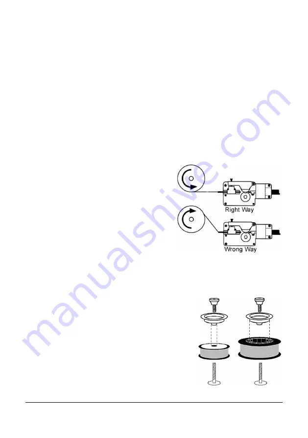
Place the spool on the spindle so the wire is
straight, not at an angle, when it enters the
welding unit mechanism (Fig. 4).
5.
The purpose of the drive brake is to halt the
spool of wire at nearly the same moment that
wire feeding stops.
a.
Four Inch Wire Spool - Install the drive
brake hardware on the top of the spool
of wire, as shown in Fig. 5-A.
A
B
Fig. 5
Fig. 4


