background image

23

INSTALLATION STEP 11

Fasten the Door Bracket 

Follow instructions which apply to your door type 
as illustrated below or on the following page.

A horizontal reinforcement brace should be long 
enough to be secured to two or three vertical supports. 
A vertical reinforcement brace should cover the height 
of the top panel. 

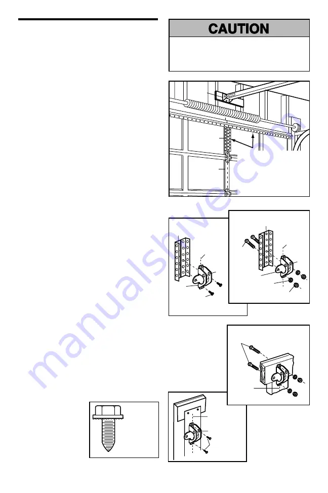
Figure 1 shows one piece of angle iron as the horizontal 
brace. For the vertical brace, 2 pieces of angle iron are 
used to create a U-shaped support. The best solution is to 
check with your garage door manufacturer for an opener 
installation door reinforcement kit.

NOTE: 

Many door reinforcement kits provide for direct 

attachment of the clevis pin and door arm. In this case 
you will not need the door bracket; proceed to Step 12.

SECTIONAL DOORS

1.   Center the door bracket on the previously marked 

vertical centerline used for the header bracket 
installation. Note correct UP placement, as stamped 
inside the bracket.

2.   Position the top edge of the bracket 2"-4" (5-10 cm) 

below the top edge of the door, OR directly below any 
structural support across the top of the door.

3.    Mark, drill holes and install as follows, depending on 

your door’s construction:

Metal or light weight doors using a vertical angle iron 
brace between the door panel support and the door 
bracket: 

•   Drill 3/16" fastening holes. Secure the door bracket 

using the two 1/4"-14x5/8" self-threading screws 
(Figure 2A).

•   Alternately, use two 5/16" bolts, lock washers and nuts 

(not provided) (Figure 2B).

Metal, insulated or light weight factory reinforced 
doors: 

•   Drill 3/16" fastening holes. Secure the door bracket 

using the self-threading screws (Figure 3).

Wood Doors:

•   Use top and bottom or side to side door bracket holes. 

Drill 5/16" holes through the door and secure bracket 
with 5/16"x2" carriage bolts, lock washers and nuts 
(not provided) (Figure 4).

NOTE: 

The 1/4"-14x5/8" self-threading screws are not 

intended for use on wood doors.

Fiberglass, aluminum or lightweight steel garage 
doors 

WILL REQUIRE

 reinforcement BEFORE 

installation of door bracket. Contact your door 
manufacturer for reinforcement kit.

HORIZONTAL AND VERTICAL 
REINFORCEMENT IS NEEDED 
FOR LIGHTWEIGHT GARAGE 
DOORS (FIBERGLASS, 
ALUMINUM, STEEL, DOORS 
WITH GLASS PANEL, ETC). 
(NOT PROVIDED)

Figure 1

Figure 2A

Figure 3

Figure 4

Figure 2B

HARDWARE
SHOWN
ACTUAL SIZE

Header 
Bracket

Door 
Bracket 
Location

Vertical 
Centerline 
of Garage 
Door

Vertical 
Reinforcement

Vertical 
Reinforcement

Vertical 
Centerline 
of Garage 
Door

Vertical 
Centerline of 
Garage Door

UP

Self-Threading 
Screw 
1/4"-14x5/8"

Self-Threading 
Screw 
1/4"-14x5/8"

Vertical 
Centerline of 
Garage Door

Door 
Bracket

Self-Threading 
Screw 1/4"-14x5/8"

UP

UP

Nut 
5/16"-18

Lock 
Washer
5/16"

Door 
Bracket

Bolt 
5/16"-18x2" 
(Not 
Provided)

Vertical 
Centerline 
of Garage 
Door

UP

Bolt 5/16"x2" 
(Not Provided)

Inside Edge 
of Door or 
Reinforcement 
Board

Содержание PD752DS 3/4 HP

Страница 1: ...ial Use Only Owner s Manual Please read this manual and the enclosed safety materials carefully Fasten the manual near the garage door after installation The door WILL NOT CLOSE unless The Protector System is connected and properly aligned Periodic checks of the opener are required to ensure safe operation The model number label is located on the left side panel of your opener ...

Страница 2: ...1 To open the door manually 31 Care of your garage door opener 32 Having a problem 33 Diagnostic chart 34 Programming 35 36 To add or reprogram a hand held remote control 35 To erase all codes 35 3 Button remotes 35 To add reprogram or change a Keyless Entry PIN 36 Repair Parts 37 38 Rail assembly parts 37 Installation parts 37 Motor unit assembly parts 38 Accessories 39 Repair Parts and Service 4...

Страница 3: ...ble locks BEFORE installing and operating the opener ONLY operate garage door opener at 120V 60 Hz to avoid malfunction and damage Sectional Door One Piece Door Carpenter s Level Optional Tape Measure Pencil Wire Cutters Hack Saw Claw Hammer Adjustable End Wrench Screwdriver Pliers Drill Stepladder Sockets and Wrench 1 2 5 8 7 16 9 16 and 1 4 Drill Bits 3 16 5 16 and 5 32 Preparing your garage doo...

Страница 4: ...or must not exceed 1 4 6 mm Otherwise the safety reversal system may not work properly See Adjustment Step 3 Floor or door should be repaired SECTIONAL DOOR INSTALLATIONS Do you have a steel aluminum fiberglass or glass panel door If so horizontal and vertical reinforcement is required Installation Step 11 The opener should be installed above the center of the door If there is a torsion spring or c...

Страница 5: ...NOT work properly The floor or the garage door MUST be repaired to eliminate the gap FINISHED CEILING CLOSED POSITION Trolley Stop Bolt Cable Chain Rail Emergency Release Rope Handle Curved Door Arm Straight Door Arm Door Bracket Garage Door Header Bracket Header Wall CLOSED POSITION Trolley Stop Bolt Cable Trolley Rail Header Bracket Door Bracket Straight Door Arm Garage Door Header Wall Curved Do...

Страница 6: ...ry Motion Detecting Door Control Panel SECURITY 3 Button Remote Control with Visor Clip 2 SECURITY Keyless Entry Models PD752KLDS PD752KDS Chain and Cable Safety Labels and Literature U Bracket Hanging Brackets Door Bracket 2 Conductor Bell Wire White White Red Curved Door Arm Section Straight Door Arm Section Header Bracket Motor Unit with 2 Light Lenses Idler Pulley Chain Spreader Rail Center Ba...

Страница 7: ...ge Bolt 1 4 20x1 2 2 Lag Screw 5 16 9x1 5 8 2 Lag Screw 5 16 18x1 7 8 2 Self Threading Screw 1 4 14x5 8 2 Drywall Anchors 2 Clevis Pin 5 16 x1 1 4 1 Clevis Pin 5 16 x1 1 2 1 Clevis Pin 5 16 x1 1 Rope Screw 6ABx1 1 4 2 Screw 6 32x1 2 Hex Bolt 5 16 18x7 8 4 Lock Washer 5 16 7 Insulated Staples 30 Wing Nut 1 4 20 2 Ring Fastener 3 Nut 5 16 18 8 Handle Idler Bolt 1 Spacer 1 Bolt 1 4 20x1 3 4 1 Bolt 1 ...

Страница 8: ...own and slide the tapered ends into the larger ones Tabs along the side will lock into place 3 Place the motor unit on packing material to protect the cover and rest the back end of the rail on top For convenience put a support under the front end of the rail 4 As a temporary trolley stop insert a screwdriver into the hole 10 25 cm away from the front of the rail as shown 5 Check to be sure there ...

Страница 9: ...TO STOPS ON TOP AND SIDES OF BRACKET U Bracket HARDWARE SHOWN ACTUAL SIZE Spacer Washer 5 8 Lock Nut 1 4 20 ASSEMBLY STEP 3 Install the Idler Pulley Lay the chain cable beside the rail as shown Grasp the end with the cable loop and pass approximately 12 30 cm of cable through the window Allow it to hang until Assembly Step 5 Remove the tape from the idler pulley The inside center should be pre gre...

Страница 10: ...he remaining master link 5 Thread the inner nut and lock washer onto the trolley threaded shaft Figure 3 6 Insert the trolley threaded shaft through the hole in the trolley Be sure the chain is not twisted Figure 4 7 Loosely thread the outer nut onto the trolley threaded shaft 8 Remove the screwdriver To avoid possible SERIOUS INJURY to fingers from moving garage door opener ALWAYS keep hand clear ...

Страница 11: ...icated garage door An improperly balanced door may NOT reverse when required and could result in SEVERE INJURY or DEATH 3 ALL repairs to cables spring assemblies and other hardware MUST be made by a trained door systems technician BEFORE installing opener 4 Disable ALL locks and remove ALL ropes connected to garage door BEFORE installing opener to avoid entanglement 5 Install garage door opener 7 ...

Страница 12: ...for the top edge of the door NOTE If the total number of inches exceeds the height available in your garage use the maximum height possible or refer to page 13 for ceiling installation To prevent possible SERIOUS INJURY or DEATH Header bracket MUST be RIGIDLY fastened to structural support on header wall or ceiling otherwise garage door might NOT reverse when required DO NOT install header bracket...

Страница 13: ...LATION Extend the vertical centerline onto the ceiling as shown Center the bracket on the vertical mark no more than 6 15 cm from the wall Make sure the arrow is pointing away from the wall The bracket can be mounted flush against the ceiling when clearance is minimal Mark the side holes Drill 3 16 pilot holes and fasten bracket securely to a structural support with the hardware provided Header Bra...

Страница 14: ... ladder is not tall enough Open the door all the way and place a 2x4 laid flat on the top section beneath the rail If the top section or panel hits the trolley when you raise the door pull down on the trolley release arm to disconnect inner and outer sections Slide the outer trolley toward the motor unit The trolley can remain disconnected until Installation Step 12 is completed ONE PIECE DOOR WITH...

Страница 15: ...n line with the header bracket if the bracket is not centered above the door 7 Remove the 2x4 Operate the door manually If the door hits the rail raise the header bracket NOTE DO NOT connect power to opener at this time To avoid possible SERIOUS INJURY from a falling garage door opener fasten it SECURELY to structural supports of the garage Concrete anchors MUST be used if installing ANY brackets ...

Страница 16: ...ick connect terminals as follows white to white and white red to red Figure 4 NOTE When connecting multiple door controls to the opener twist same color wires together Insert wires into quick connect holes white to white and red white to red 5 Use tacks or staples to permanently attach entrapment warning label to wall near door control and manual release safety reverse test label in a prominent lo...

Страница 17: ... other end of the rope through the hole in the release arm of the outer trolley Adjust rope length so the handle is 6 feet 1 83 m above the floor Ensure that the rope and handle clear the tops of all vehicles to avoid entanglement Secure with an overhand knot NOTE If it is necessary to cut the rope heat seal the cut end with a match or lighter to prevent unraveling To prevent possible OVERHEATING o...

Страница 18: ...d Connect the black line wire to the screw on the brass terminal the white neutral wire to the screw on the silver terminal and the ground wire to the green ground screw The opener must be grounded Reinstall the cover To avoid installation difficulties do not run the opener at this time To prevent possible SERIOUS INJURY or DEATH from electrocution or fire Be sure power is NOT connected to the opene...

Страница 19: ...are designed to clip onto the track of sectional garage doors without additional hardware If it is necessary to mount the units on the wall the brackets must be securely fastened to a solid surface such as the wall framing Extension brackets see accessories are available if needed If installing in masonry construction add a piece of wood at each location to avoid drilling extra holes in masonry if...

Страница 20: ...l with lag screws not provided If using extension brackets or wood blocks adjust right and left assemblies to the same distance out from the mounting surface Make sure all door hardware obstructions are cleared Floor installation Figure 4 Use wood blocks or extension brackets see accessories to elevate sensor brackets so the lenses will be no higher than 6 15 cm above the floor Carefully measure an...

Страница 21: ...follow the instructions below Cut the end of the safety reversing sensor wire making sure there is enough wire to reach the pre installed wires from the wall Figure 7 Separate the safety reversing sensor wires and strip 7 16 11 mm of insulation from each end Choose two of the pre installed wires and strip 7 16 11 mm of insulation from each end Make sure that you choose the same color pre installed...

Страница 22: ...correct wiring between sensors and opener A broken wire 2 If the sending eye indicator light glows steadily but the receiving eye indicator light doesn t Check alignment Check for an open wire to the receiving eye 3 If the receiving eye indicator light is dim realign either sensor NOTE When the invisible beam path is obstructed or misaligned while the door is closing the door will reverse If the d...

Страница 23: ...ng holes Secure the door bracket using the two 1 4 14x5 8 self threading screws Figure 2A Alternately use two 5 16 bolts lock washers and nuts not provided Figure 2B Metal insulated or light weight factory reinforced doors Drill 3 16 fastening holes Secure the door bracket using the self threading screws Figure 3 Wood Doors Use top and bottom or side to side door bracket holes Drill 5 16 holes thr...

Страница 24: ...cket Vertical Centerline of Garage Door Nut 5 16 18 HARDWARE SHOWN ACTUAL SIZE Self Threading Screw 1 4 14x5 8 ONE PIECE DOORS Please read and comply with the warnings and reinforcement instructions on the previous page They apply to one piece doors also Center the door bracket on the top of the door in line with the header bracket as shown Mark either the left and right or the top and bottom hole...

Страница 25: ...ve holes in straight arm disconnect straight arm Cut about 6 15 cm from the solid end Reconnect to trolley with cut end down as shown Bring arm sections together Find two pairs of holes that line up and join with bolts lock washers and nuts Pull the emergency release handle toward the opener at a 45 angle so that the trolley release arm is horizontal Proceed to Adjustment Step 1 page 27 Trolley wi...

Страница 26: ...or control push button The trolley will travel to the fully closed position Manually close the door and lift the door arm to the trolley The arm should touch the trolley just ahead of the door arm connector hole Refer to the fully closed trolley door arm positions in the illustration If the arm is behind the connector hole adjust the limit further One full turn equals 3 7 5 cm of trolley travel 3 ...

Страница 27: ... force as explained in Adjustment Step 2 If the door does not close completely Increase down travel Turn the down limit adjustment screw counterclockwise One turn equals 3 7 5 cm of travel If door still won t close completely and the trolley bumps into the pulley bracket page 4 try lengthening the door arm page 25 and decreasing the down limit If the opener reverses in fully closed position Decrea...

Страница 28: ...orce by turning the control clockwise Make small adjustments until the door completes a close cycle After each adjustment run the opener through a complete travel cycle Do not increase the force beyond the minimum amount required to close the door 2 Test the UP open force Grasp the door bottom when the door is about halfway through UP open travel The door should stop If the door is hard to hold or...

Страница 29: ...nt of the opener ADJUSTMENT STEP 4 Test The Protector System Press the remote control push button to open the door Place the opener carton in the path of the door Press the remote control push button to close the door The door will not move more than an inch 2 5 cm and the opener lights will flash The garage door opener will not close from a remote if the indicator light in either sensor is off ale...

Страница 30: ...r opener will operate with up to eight Security remote controls and one Security Keyless Entry System If you purchase a new remote or if you wish to deactivate any remote follow the instructions in the Programming section Activate your opener with any of the following The hand held Remote Control Hold the large push button down until the door starts to move The wall mounted Door Control Hold the p...

Страница 31: ...ol the Outside Keylock and the Keyless Entry Accessories To activate press and hold the Lock button for 2 seconds The push bar light will flash as long as the Lock feature is on To turn off press and hold the Lock button again for 2 seconds The push bar light will stop flashing The Lock feature will also turn off whenever the Learn button on the motor unit panel is activated Push Bar Lock Button Lig...

Страница 32: ...t grease the door tracks NOTICE To comply with FCC and or Industry Canada IC rules adjustment or modifications of this receiver and or transmitter are prohibited except for changing the code setting or replacing the battery THERE ARE NO OTHER USER SERVICEABLE PARTS Tested to Comply with FCC Standards FOR HOME OR OFFICE USE Operation is subject to the following two conditions 1 this device may not ...

Страница 33: ... adjustments to force or travel limits The need for occasional adjustment for the force and limit settings is normal Weather conditions in particular can affect door travel Refer to Adjustment Step 1 Adjust the UP and DOWN Travel Limits Decrease down travel by turning down limit adjustment screw clockwise 5 My lights will not turn off when door is open The garage door opener is equipped with a sec...

Страница 34: ...not activate disconnect door control wires from motor unit Momentarily short across red and white terminals with jumper wire If motor unit activates replace door control wires Symptom Sending indicator light glows steadily receiving indicator light is dim or flashing Realign receiving eye sensor clean lens and secure brackets Verify door track is firmly secured to wall and does not move Symptom Moto...

Страница 35: ...perated with a non rolling code transmitter the technical measure in the receiver of the garage door opener which provides security against code theft devices will be circumvented The owner of the copyright in the garage door opener does not authorize the purchaser or supplier of the non rolling code transmitter to circumvent that technical measure Your garage door opener has already been programm...

Страница 36: ...N has been learned Test by pressing the new PIN then press Enter The door should move To set a temporary PIN You may authorize access by visitors or service people with a temporary 4 digit PIN After a programmed number of hours or number of accesses this temporary PIN expires and will no longer open the door It can be used to close the door even after it has expired To set a temporary PIN 1 Press ...

Страница 37: ...p 5 41A2828 Emergency release rope and handle assembly 6 41B4494 1 2 Conductor bell wire white and white red 7 41A5047 1 Door bracket with clevis pin fastener 8 41A5047 2 Header bracket with clevis pin fastener 9 41A5034 Safety reversing sensor kit receiving and sending eyes with 3 9 m 2 conductor bell wire 10 178B34 Straight door arm section 11 12B776 Hanging bracket 12 178B35 Curved door arm sec...

Страница 38: ...assembly RPM sensor KEY PART NO NO DESCRIPTION 10 41A5633 2 Cover 11 41A2818 Limit switch drive retainer 12 41D3452 2 Limit switch assembly 13 41A2822 1 Interrupter cup 14 41C4398A RPM sensor assembly 15 41AC075 2S Receiver logic board assembly Complete with Logic board end panel with all labels light socket 16 41C5588 High voltage wire harness 41C6661 Low voltage wire harness 17 41D180 1 End pane...

Страница 39: ...omatically turns opener lights on for 5 minutes when it detects a person entering the garage Sensor can be easily deactivated when desired CLDM1 Garage Door Monitor Monitors the status of your garage door from inside your home 7702CB Outside Quick Release Required for a garage with NO access door 760CB Outdoor Key Switch Opens the garage door automatically from outside when remote control is not h...

Страница 40: ... will be repaired or replaced at Seller s sole option at no cost to you and returned pre paid Defective parts will be repaired or replaced with new or factory rebuilt parts at Seller s sole option ALL IMPLIED WARRANTIES FOR THE PRODUCT INCLUDING BUT NOT LIMITED TO ANY IMPLIED WARRANTIES OF MERCHANTABILITY AND FITNESS FOR A PARTICULAR PURPOSE ARE LIMITED IN DURATION TO THE ONE YEAR LIMITED WARRANTY...

Отзывы: