Powered by Safety
®
42
Usage
01.4IB.48041
BriteSpot
®
Plus
Table W Example Relay Trigger Data
Input Register Address
(Name)
Dec
Hex
Binary
30051 (Relay 1 Inputs)
142
0x 008E 0b 0000 0000 1000 1110
In the case above, the bits that are set
indicate that Relay 1 can be triggered by
alarms 2, 3, 4, and 8.
d. d
AtA
l
oG
The Data Log allows the user to visualize and
download temperature logs for data analysis
and trend recognition.
1) Log Rate and Time Span
There is a fixed amount of memory
available on the device for storage of
the data log. The maximum number
records that can be stored is 16,777,215.
The data collection interval can be set
to any duration in minutes greater than
1. Increasing the frequency of the data
collection affects the time span for which
data can be collected. At a logging interval
of 1 minute, roughly 32 years of data can be
recorded.
e. f
Actory
r
eSet
Under some circumstances it may be desirable
to return the BriteSpot® Plus back to the factory
configuration. In such situations, perform the
following reset procedure:
1. Navigate to the settings page of the UI.
2. Select “Reboot” and press enter.
3. Once the unit begins to reboot, hold down
the left most two buttons.
4. Upon reboot, there will be two beeps
indicating the unit was restored to its
factory settings successfully.
Note: Restoring to factory settings will erase
all user alarm settings.
f. f
irmWAre
u
ploAd
p
rocedure
for
B
rite
S
pot
®
p
luS
In order to perform a firmware upgrade of the
BriteSpot Plus the following tools are required:
• Bootloader software, most current version,
64 or 32 bit:
• 60092-sw-bootloader-rev-x.xx.xx.x64
• 60092-sw-bootloader-rev-x.xx.xx.x86
• USB A to mini B cable
• Firmware .hex file
• Computer
Note: The bootloader software currently
operates on Windows 7 only.
The following describes the firmware upload
procedure:
1. Install the appropriate version of the
bootloader software on the computer
(60092-sw-bootloader-rev-x.xx.xx.x64 for
64 bit Windows and 60092-sw-bootloader-
rev-x.xx.xx.x86 for 32 bit Windows).
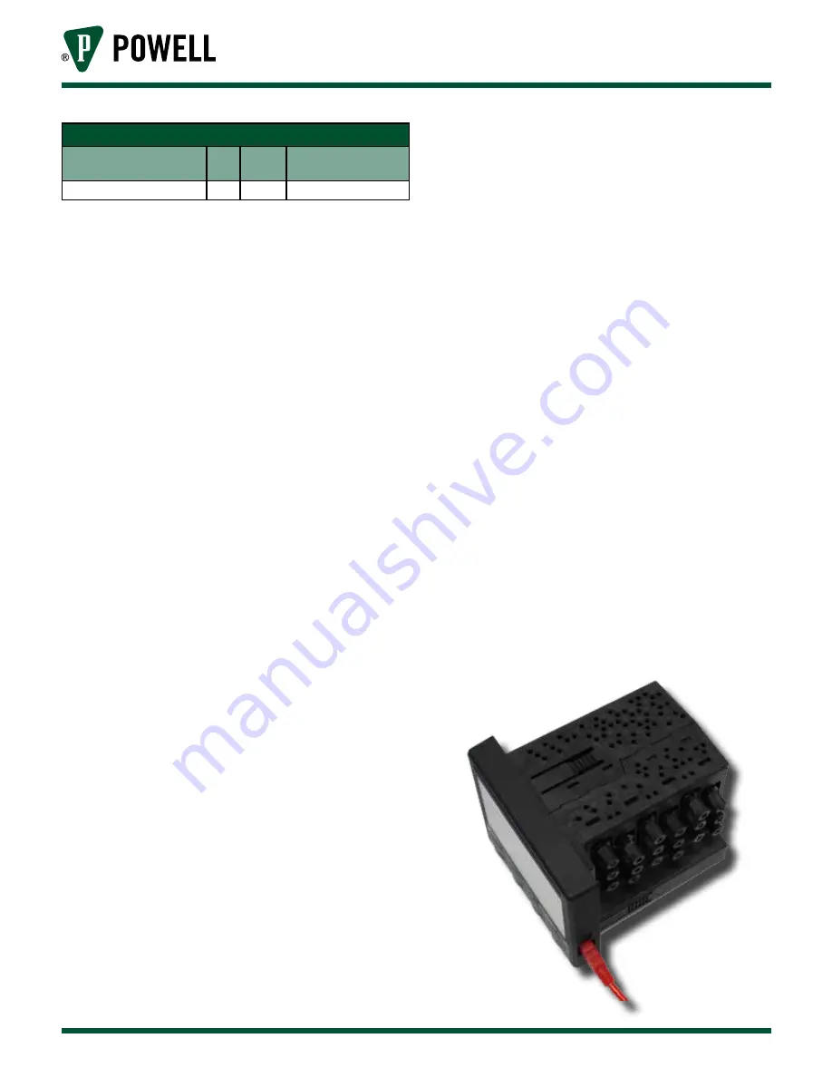
2. Connect the USB cable between the
computer and the BriteSpot Plus (
).
Figure 57 USB Cable Connection
Содержание BriteSpot Plus
Страница 4: ...Powered by Safety 01 4IB 48041 BriteSpot Plus This page is left blank intentionally ...
Страница 29: ...Powered by Safety 19 Installation 01 4IB 48041 Figure 20 Panel Mount Clip Installation X X ...
Страница 57: ...Powered by Safety 47 Appendix A 01 4IB 48041 Figure 64 10250 BSPL 18C1P1E0X0 Dimensions ...
Страница 58: ...Powered by Safety 48 Appendix A 01 4IB 48041 BriteSpot Plus Figure 65 10251 BSPL 09C1P E0X0 Dimensions ...


