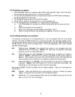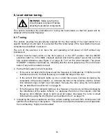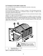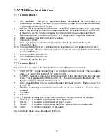
1.4. Front panel controls and indicators
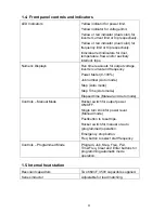
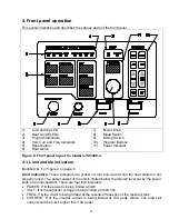
LED Indicators
Yellow indicator for power limit.
Yellow indicator for voltage limit.
Yellow or red indicator (dual color) for
inverter current limit or trip respectively.
Yellow or red indicator (dual color) for
frequency limit or trip respectively.
Individual red indicators for door,
temperature, flow and/or auxiliary
interlock trips.
Numeric Displays
Run time read-outs for output voltage,
inverter current and frequency
Power Meter (0-100%)
Job number (Auto mode)
Step (Auto mode)
Step Time (Auto mode)
Elapsed time (Manual and Auto mode)
Controls – Manual Mode
Rocker switch for output power
ON/OFF.
Single turn knob for power level.
(Manual mode)
Pushbutton to reset trips.
Rocker switch for manual or auto
(programmed) operation.
Emergency stop button.
Freq button to select start frequency
Controls – Programmed Mode
Program, Job, Step, Freq, Pwr,
Time/Freq, Clear and Enter buttons for
programming automatic mode
operation.
1.5. Internal heat station
Resonant capacitors
Two 660nF, 350V capacitors supplied.
Series inductor
Adjustable for load matching.
4


