background image

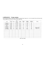
8. APPENDIX B: 

Tuning examples 

The following examples are intended as a guideline for tuning the power supply only.  It is recommended that users add examples 
of their applications to this list as a reference future applications.  
 

Load 

Caps (

μ

F) 

Taps 

Coil 

(# turns 

x I.D.) 

Freq 

(kHz) 

Power 

(kW) 

Voltage 

(Vrms) 

Inverter 

Current 

Notes 

1” steel pipe 

1.320 

4 x 2.5” 

165 

180 

74 


1” steel pipe 

1.320 

2 x 2.5” 

223 

160 

54 


1” steel pipe 

1.320 

1 x 2.5” 

349 

2.9 

183 

70 


Open 

1.320 

5 x 3/4” 

308 

230 

44 


1” steel pipe 

1.320 

3 x 1.5” 

324 

90 

70 


1” steel pipe 

0.660 

5  

3 x 1.5” 

392 

1.2 

70 

24 

Frequency limit 

1”steel pipe 

0.210 

10 

8 x 4” 

256 

2.3 

500 

65 

Capacitor limit 

.2” x 1/2” stud 

1.320 

3 x 3/4” 

300 

230 

70 


 3kW Power Supply 


18 
Содержание 3-135/400-3W

Страница 1: ...Induction Power Supplies 3kW 135 400kHz Integral Heat Station User s Guide Model 3 135 400 3 Model 3 135 400 3W Rev E 12 1 04 ...

Страница 2: ... 9 4 2 Heat ON OFF indicators 10 4 3 Program status indicators 10 4 4 Voltage Current and Frequency Indicators 10 4 5 Reset Button 10 4 6 Heat switch 10 4 7 Power Pot 10 4 8 MODE switch 11 4 9 E Stop button 11 4 10 Program buttons 11 4 11 Power Display Indicator 11 4 12 Start frequency adjustment 11 4 13 Feedback selection 12 5 PROGRAMMING IN AUTO MODE 13 5 1 Entering a program 13 5 2 Running a pr...

Страница 3: ...nse Time 0 1s3 Minimum Allowed OFF Time 0 5s 1 2 Input AC line to line voltage 208V 240V 10 50 to 60Hz AC line current 14 5A 230V AC power 3 6kVA 1 3 Physical Dimensions Length Width Height 20 5in 521mm 11 7in 297mm 12 7in 323mm Weight 43 5lb 20kg 1 3kW is output power 3 6kVA input power allows for losses in the power supply 2 Limited by rating of resonant capacitors 3 When using the adjustable st...

Страница 4: ...er current and frequency Power Meter 0 100 Job number Auto mode Step Auto mode Step Time Auto mode Elapsed time Manual and Auto mode Controls Manual Mode Rocker switch for output power ON OFF Single turn knob for power level Manual mode Pushbutton to reset trips Rocker switch for manual or auto programmed operation Emergency stop button Freq button to select start frequency Controls Programmed Mod...

Страница 5: ...otection Safety Interlocks Emergency stop button or door switch opens the main circuit breaker 1 7 Load Quality factor of load Will operate with any load Q including resistive loads provided that the output frequency and voltage is within the specifications 1 8 Cooling Water Maximum pressure 100PSI 690kPa Minimum differential pressure 30PSI 207kPa Minimum water flow 5GPM 0 032l s Maximum inlet wat...

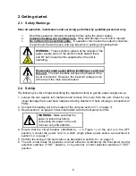
Страница 6: ...p The following is a list of steps describing the required actions to get the power supply set up 1 Loosen the two quarter turn fasteners and remove the cover from the unit Check for any visual damage that could have happened during shipment Check all plug in connectors of PCBs 2 Connect the heating coil to the output of the unit see section 3 1 on page 7 3 Read section 4 on page 9 to become famil...

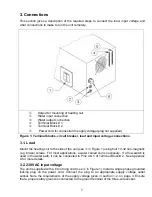
Страница 7: ...to the side of the unit see 1 in Figure 1 using four 10 32 non magnetic e g brass screws For most applications a water cooled coil is necessary If a flow switch is used in the water path it can be connected to Pins 4 5 of Terminal Block 2 See Appendix A for more details 3 2 230VAC input voltage The unit is supplied with a 6 foot long cord see 2 in Figure 1 Install a single phase grounded locking p...

Страница 8: ...remote power reference see 4 in Figure 1 on page 7 The lower three terminals can be used to interface the power supply with a computer APPENDIX A User Interface on page 17 explains the connections in more detail 3 5 Terminal Block 2 Heat On E Stop Auxiliary Interlock and Reset functions can be run remotely from this terminal block There are also relay contacts for Heat On Power Supply Fault and Po...

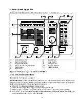
Страница 9: ... 1 in Figure 2 on page 9 Limit indicators These indicators are yellow in color and are lit when the heat station is not properly tuned The power output of the unit is limited below the desired level set by the power knob or remote pendant There are four limit indicators POWER If lit the power is being limited at 3kW VOLT If lit the capacitor voltage is being limited at 350V rms FREQ If lit the cir...

Страница 10: ...he AUTO mode The STEP TIME indicator display minutes and the ELAPSED TIME indicator displays seconds during manual mode operation 4 4 Voltage Current and Frequency Indicators Identified by 3 in Figure 2 on page 9 These read outs display the output voltage the inverter current and the operating frequency when the power supply is operating 4 5 Reset Button Identified by g in Figure 2 on page 9 This ...

Страница 11: ...y 11 in Figure 2 on page 9 This read out displays the demand power when the unit is in standby or program mode and displays the power output when the heat cycle is in progress 4 12 Start frequency adjustment The Power Supply starts at a frequency above 400kHz To generate power it lowers the frequency until the operating frequency is near yet still above the resonance point of the tank circuit If t...

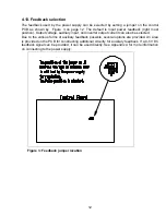
Страница 12: ...e auxiliary input and inverter output current can also be selected Due to the various forms of auxiliary feedback possible several options are provided An area is provided on the PCB for constructing additional circuitry for auxiliary feedback If a 0 5V DC feedback signal can be provided it can be used directly See Appendix A for more information on connecting to the power supply Figure 3 Feedback...

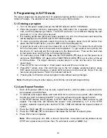
Страница 13: ...s to enter a time up to 640 seconds For longer intervals several steps in a row can be set to the same power level 7 Press STEP to move to step 2 Enter power level and time as in step six 8 Press ENT enter once this will bring you to the Ar display explained later press ENT again to record changes or press JOB to move onto the next job Note If no Job has been programmed an AUX trip indicator will ...

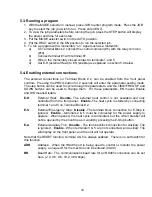
Страница 14: ...ME FREQ UP and DOWN buttons can be used to change them For these parameters EN means Enable and DIS means Disable E H External Heat Disable The external heat control is not available and only controlled from the front panel Enable The heat cycle is started by connecting terminal 1 and 5 on Terminal Block 2 E S External Emergency Stop Disable The terminal block connection for E Stop is ignored Enab...

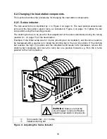
Страница 15: ...reset button if any red trip indicators are lit 2 Put the HEAT switch in the ON position If the unit is not delivering full power and the frequency is indicated as 135kHz no limit indicators will be lit the tank frequency is outside the range of the unit If the current limit indicator lights up or a current trip occurs continue increasing the inductance of the series inductor i e increase the turn...

Страница 16: ...g the tuning section 6 1 on page 15 of the heat station Example If the initial setup was for 4 turns shorting bar not installed and the turns needs to be decreased with a quarter turn install the shorting bar in the low 3 position If the shorting bar reaches the high 1 position and the inductance still needs to be decreased remove the shorting bar completely and move the turns bar one position for...

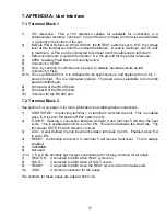
Страница 17: ...400 baud to 38400 baud 8 Terminal A of the RS 485 port 9 Terminal B of the RS 485 port 10 Common for the RS 485 port 7 2 Terminal Block 2 See section 5 4 on page 14 for more information on enabling these connections 1 START STOP Connecting terminal 1 to terminal 5 will start the unit This is enabled when E H is set to EN and the HEAT switch is ON 2 E STOP Opening a connection between terminal 2 an...

Страница 18: ... turns x I D Freq kHz Power kW Voltage Vrms Inverter Current Notes 1 steel pipe 1 320 8 4 x 2 5 165 3 180 74 1 steel pipe 1 320 7 2 x 2 5 223 3 160 54 1 steel pipe 1 320 5 1 x 2 5 349 2 9 183 70 Open 1 320 8 5 x 3 4 308 3 230 44 1 steel pipe 1 320 3 3 x 1 5 324 3 90 70 1 steel pipe 0 660 5 3 x 1 5 392 1 2 70 24 Frequency limit 1 steel pipe 0 210 10 8 x 4 256 2 3 500 65 Capacitor limit 2 x 1 2 stud...

Отзывы: