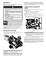
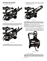
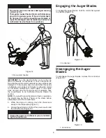
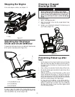
background image

5

Setup

Loose Parts

Use the chart below to verify that all parts have been shipped.

 Procedure Description 

Qty. 

Use 

1. 

No parts required

Unfold the handle. 

2. 

Carriage bolts 
Flange nuts
Washers
Knob
Chute
Deflector


4
2
1
1
1

Install the discharge chute. 
Install the discharge chute.

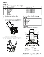
1. Unfolding the Handle

Procedure

1.   Loosen the two handle knobs and pull out the two 

handle bolts until you can move the handle freely and 

rotate the handle to the operating position (Figure 2).

2.    Tighten the handle knobs until they are snug (Figure 3).

2. Installing the Discharge

Chute

5

Carriage bolts

4 Flange 

nuts 

2

Washers

1

Knob

1

Chute

1

Deflector

Procedure

Install the discharge chute as shown (Figure 4).

IMPORTANT: 

Do not overtighten the flange nuts; 

otherwise you may damage the discharge chute.

Figure 3

1. Handle knobs       2. Handle bolt

Figure 2

2

1

Figure 4

 1. Deflector  


2. Carriage bolts 
3. Flange nuts   

2

6

3

3 4

4 5

1

4. Washer
5. Knob  


6. Discharge chute

Содержание 436414

Страница 1: ...ways Wear Eye Protection During Operation IMPORTANT MANUAL Do Not Throw Away WARNING Read the Owner s Manual and follow all Warnings and Safety Instructions Failure to do so can result in serious inju...

Страница 2: ...ove all doormats sleds boards wires and other foreign objects 2 Disengage all clutches and shift into neutral before starting the engine motor if equipped 3 Donotoperatetheequipmentwithoutwearingadequ...

Страница 3: ...rting the engine and for transporting the snow thrower in or out of the building Open the outside doors exhaust fumes are dangerous 8 Exercise extreme caution when operating on slopes 9 Neveroperateth...

Страница 4: ...in literature supplied with the product Learn and under stand their meaning IMPORTANT Safety and instruction decals are located near areas of potential danger Replace damaged decals 2 2 7 2 2 7 3 49...

Страница 5: ...dle knobs and pull out the two handle bolts until you can move the handle freely and rotate the handle to the operating position Figure 2 2 Tightenthehandleknobsuntiltheyaresnug Figure3 2 Installing t...

Страница 6: ...tic oil is acceptable for use in cold temperatures 1 Move the snowthrower to a level surface 2 Clean around the dipstick Figure 6 NOTE Dipstick location may vary depending on engine type 3 Remove eith...

Страница 7: ...o the gasoline IMPORTANT Do not use E85 blended fuels This engine is not E20 E30 E85 compatible Alternative fuels with high alcohol content can cause hard starting poor engine performance and may caus...

Страница 8: ...r or the choke if the engine has been running and is hot Excessive priming may flood the engine and prevent it from starting 4 Connect an extension cord to the snowthrower and plug the other end into...

Страница 9: ...he electric starter extensively can overheat and damage it If the engine does not start after this series of attempts wait at least 40 minutes to allow the starter to cool before attempting to start i...

Страница 10: ...hute left and right to free it from any ice buildup With the ignition key in the Off position pull the recoil starter handle several times or connect the electrical cord to a power source and the snow...

Страница 11: ...right sides of the machine from the normal operating position The best time to remove snow is the early morning At this time the snow is usually dry and has not been exposed to the direct sun and warm...

Страница 12: ...adjusted to position 2 ensure that the auger stops properly when the control bar is released Inspecting the Auger Blades Before each session inspect the auger blades for wear When a auger blade edge h...

Страница 13: ...fully pour oil into the oil fill hole until Full on the fill cap dipstick line Figure 26 Maxfill 18oz 0 5l type automotivedetergentoilwith an API service classification of SJ SL or higher Use Figure 2...

Страница 14: ...IMPORTANT Replace a cracked fouled or dirty spark plug Do not clean the electrodes because grit entering the cylinder can damage the engine 11 Set the gap on the plug to 0 030 inch 0 76 mm Figure 30...

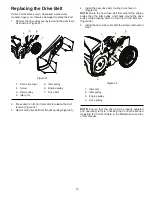
Страница 15: ...new drive belt first around the engine pulley then the idler pulley and finally around the drive pulley while pressing down on the front of the idler arm Figure 32 5 Install the drive side cover with...

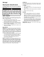
Страница 16: ...by starting the engine and letting it run until the fuel lines and carburetor are empty Never use engine or carburetor cleaner products in the fuel tank or permanent damage may occur Use fresh fuel n...

Страница 17: ...Engine idles or 1 Choke is in FULL position 1 Move choke to OFF position runs roughly 2 Blockage in fuel line 2 Clean fuel line 3 Stale fuel 3 Empty fuel tank carburetor refill with fresh clean gasoli...

Страница 18: ...ent dimensions given in U S inches 1 inch 25 4 mm IMPORTANT Use only Original Equipment Manufacturer O E M replacement parts Failure to do so could be hazardous damage your snow thrower and void your...

Страница 19: ...ETING PLASTIC W GRV 2 434876X431 2 PLATE CHUTE RETAINER 3 434875X431 1 PLATE CHUTE BASE 4 17411312 6 BOLT HEX WSH HD 13 16 X 3 4 5 434885X428 1 HANDLE CHUTE MS428 6 73970500 4 NUT LOCK HX W INS 5 16 1...

Страница 20: ...inches 1 inch 25 4 mm IMPORTANT Use only Original Equipment Manufacturer O E M replacement parts Failure to do so could be hazardous damage your snow thrower and void your warranty 1 434805X431 1 BAIL...

Страница 21: ...wer and void your warranty KEY PART NO NO QTY DESCRIPTION 1 72110407 12 BOLT CARRIAGE 2 5142H 1 PIN ROLL 3 16 X 1 1 4 3 199687 1 BOLT 1 4 20 1 50 4 434777X431 2 PLATE CENTER BLADE 5 132004 13 HEX NUT...

Страница 22: ...12 2 10 8 9 10 10 6 15 15 7 14 5 17 SSST Shroud asm_13 18 19 20 19 20 20 NOTE All component dimensions given in U S inches 1 inch 25 4 mm IMPORTANT Use only Original Equipment Manufacturer O E M repla...

Страница 23: ...428 1 COVER NON DRIVE SIDE MS428 2 435904X428 1 COVER DRIVE SIDE MS428 3 434883X421 1 TOP COVER 4 430220 1 CAP ASM FUEL 2 25 FR N CB E10 5 436235 1 BULB PRIMER 6 435407 1 KEY HOUSING 7 434867X428 1 TO...

Страница 24: ...OTE All component dimensions given in U S inches 1 inch 25 4 mm IMPORTANT Use only Original Equipment Manufacturer O E M replacement parts Failure to do so could be hazardous damage your snow thrower...

Страница 25: ...ge your snow thrower and void your warranty KEY PART NO NO QTY DESCRIPTION 1 434856 1 LCT ENGINE 2 434009X431 1 FRAME WELDMENT 3 431937X428 2 WHEEL 7X1 5 DMD GS 3SPK MS428 4 435417 2 NUT PUSH AXLE 0 5...

Страница 26: ...void your warranty KEY PART NO NO QTY DESCRIPTION 1 434860 1 SPACER ENGINE CRANK 2 434502 1 KEEPER ENGINE BELT 3 426490 1 PULLEY ENG TRACTION 3 4 4 851074 1 WASHER HARDEN 5 437261 1 BELT V TRACTION 6...

Страница 27: ...27 SERVICE NOTES...
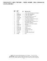
Страница 28: ...DEL NUMBER PR621 96188000100 ENGINE LCT COMPLETE ENGINE 434856 26 26A Electric Start Only 31 34 29 12 38 37 36 30 47 27 49 48 3 18 28 40 23 44 41 39 19 17 46 56 62 52 53 Included with part 40 50 22 65...

Страница 29: ...FLYWHEEL ELECTRIC START IF EQUIPPED 22A 429596 SHIELD FLYWHEEL MANUAL START IF EQUIPPED 23 420580 VALVE COVER 26 429235 ELECTRIC START FLYWHEEL ASSY IF EQUIPPED 26A 420585 MANUAL START FLYWHEEL ASSY I...

Страница 30: ...rental or commercial purposes is limited to 90 days from the date of origi nal purchase 5 This Warranty applies only to products which have been properly assembled adjusted operated and maintained in...

Отзывы: