background image

24

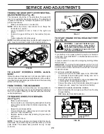
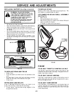
REPLACING BATTERY (

See Figs. 29 and 30

)

WARNING:  Do not short battery 

ter mi nals by allowing a wrench or any 

other object to contact both terminals 

at the same time. Before connect-

ing battery, remove metal bracelets, 

wristwatch bands, rings, etc.

Positive terminal must be connected 

first to prevent sparking from ac ci -

den tal grounding.

•  Lift seat pan to raised position.
• 

Disconnect BLACK battery cable first then RED battery 

cable and carefully remove battery from tractor.

•  Install new battery with terminals in same position as 

old battery.

• 

First connect RED battery cable to positive (+) terminal 

with hex bolt and keps nut as shown. Tighten securely. 

Slide terminal cover over terminal.

•  Connect BLACK grounding cable to negative (-) ter-

 mi nal with remaining hex bolt and keps nut. Tighten 

securely.

SERVICE AND ADJUSTMENTS

TO REPLACE HEADLIGHT BULB

• Raise 

hood.

•  Pull bulb holder out of the hole in the backside of the 

grill.

•  Replace bulb in holder and push bulb holder securely 

back into the hole in the backside of the grill.

• Close 

hood.

INTERLOCKS AND RELAYS

Loose or damaged wiring may cause your tractor to run 

poorly, stop running, or prevent it from starting.
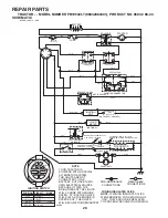
•  Check wiring.  See electrical wiring diagram in the 

Repair Parts section.

03075

HOOD

HEADLIGHT 

WIRE

CONNECTOR

FIG. 31

TO REMOVE HOOD AND GRILL ASSEMBLY 

(See Fig. 31)

• Raise 

hood.

•  Unsnap headlight wire connector.
• 

Stand in front of tractor.  Grasp hood at sides, tilt toward 

engine and lift off of tractor.

•  To replace, reverse above procedure.

FIG. 29

FIG. 30

SEAT PAN

KEPS NUT

HEX 

BOLT

POSITIVE (RED) CABLE

NEGATIVE (BLACK) CABLE

TER MI NAL 

COVER

ENGINE

TO AD JUST THROTTLE CON TROL CABLE 

The throttle control has been preset at the factory and 

ad just ment should not be necessary. If adjustment is nec-

 es sary, see engine manual.

TO AD JUST CHOKE CON TROL 

The choke control has been preset at the factory and ad-

 just ment should not be necessary. If adjustment is neces-

sary, see engne manual.

TO ADJUST CARBURETOR  

Your carburetor is not adjustable. If your engine does not 

operate properly due to suspected carburetor problems, 

take your tractor to an authorized service center for repair 

and/or adjustment.

TO REPLACE FUSE

Replace with 20 amp automotive-type plug-in fuse.  The 

fuse holder is located behind the dash.

Содержание 413420

Страница 1: ...ECTION DURING OPERATION Visit our website www poulan pro com WARNING Read this Manual and follow all Warnings and Safety Instructions Failure to do so can result in serious injury IMPORTANT MANUAL Do Not Throw Away 413420 Rev 4 04 28 08 SBW TH Printed in U S A 03076 ...

Страница 2: ...king brake stop engine and remove keys before dismounting Disengage blades when not mowing Shut off engine and wait for all parts to come to a complete stop before cleaning the machine removing the grass catcher or unclogging the discharge guard Operate machine only in daylight or good artificial light Do not operate the machine while under the influence of alcohol or drugs Watch for traffic when ...

Страница 3: ...ach towed equipment except at the hitch point Follow the manufacturer s recommendation for weight limits for towed equipment and towing on slopes Never allow children or others in or on towed equip ment On slopes the weight of the towed equipment may cause loss of traction and loss of control Travel slowly and allow extra distance to stop V SERVICE SAFE HANDLING OF GASOLINE To avoid personal injur...

Страница 4: ...aintenance and Stor age sections of this owner s manual WARNING This tractor is equipped with an internal com bustion engine and should not be used on or near any unimprovedforest covered brush coveredorgrass covered land unless the engine s exhaust system is equipped with a spark arrester meeting applicable local or state laws if any If a spark arrester is used it should be maintained in effectiv...

Страница 5: ...eering Extension Shaft Steering Wheel Adapter Steering Boot Steering Extension Shaft 2 Keys Slope Sheet Key 1 Oil Drain Tube 3TEERING 7HEEL Steering Extension Shaft Steering Wheel Adapter Steering Boot Steering Extension Shaft Seat Seat Washer Washer 1 Hex Bolt Lock Washer Insert ª OLT ...

Страница 6: ...ls as necessary to insure proper tightness FIG 1 03132 LOWER STEERING SHAFT STEERING BOOT EXTENSION SHAFT 5 16 HEX BOLT STEERING WHEEL INSERT ADAPTER LARGE FLAT WASHER TABS TAB SLOTS 5 16 LOCK WASHER BEFORE REMOVING TRACTOR FROM SKID ATTACH STEERING WHEEL See Fig 1 ASSEMBLE EXTENSION SHAFT AND BOOT Slide extension shaft onto lower steering shaft Place tabs of steering boot over tab slots in dash a...

Страница 7: ...r indicated on label label located between terminals charge battery for minimum of one hour at 6 10 amps See BATTERY in MAINTENANCE section of this manual for charging instructions INSTALL SEAT See Figs 2 and 3 Removeboltandflatwashersecuringseattocardboard packing and set aside for assembly of seat to tractor Remove the cardboard packing and discard Connect switch to seat Place seat on seat pan s...

Страница 8: ...drive belts Be sure they are routed properly around pulleys and inside all belt keepers Check wiring See that all connections are still secure and wires are properly clamped WHILE LEARNING HOW TO USE YOUR TRACTOR PAY EXTRA ATTENTION TO THE FOLLOWING IMPORTANT ITEMS Engine oil is at proper level Fuel tank is filled with fresh clean regular unleaded gasoline Become familiar with all controls their l...

Страница 9: ...s injury or death The safety alert symbol is used to identify safety inform ation about hazards which can result in death serious injury and or property damage DANGER indicates a hazard which if not avoided will result in death or serious injury WARNING indicates a hazard which if not avoided could result in death or serious injury CAUTION indicates a hazard which if not avoided might result in mi...

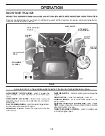
Страница 10: ...ion of the tractor Our tractors conform to the applicable safety standards of the American National Standards Institute FIG 5 PARKING PARKING BRAKE BRAKE CLUTCH BRAKE CLUTCH BRAKE PEDAL PEDAL THROTTLE CHOKE THROTTLE CHOKE CONTROL CONTROL GEAR GEAR SHIFT SHIFT LEVER LEVER ATTACHMENT ATTACHMENT LIFT LEVER LIFT LEVER IGNITION IGNITION SWITCH SWITCH ATTACHMENT ATTACHMENT CLUTCH LEVER CLUTCH LEVER ROS ...

Страница 11: ...hen leaving tractor to prevent unauthorized use Never use choke to stop engine IMPORTANT LEAVING THE IGNITION SWITCH IN ANY POSITION OTHER THAN OFF WILL CAUSE THE BATTERY TO BE DISCHARGED DEAD TO USE THROTTLE CONTROL See Fig 6 Always operate engine at full speed fast Operating engine at less than full speed fast reduces the engine s operating efficiency Full speed fast offers the best mower perfor...

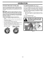
Страница 12: ...own and behind before backing Move gear shift lever to reverse R position and slowly release clutch brake pedal to start movement When use of the ROS is no longer needed turn the ignition key clockwise to engine ON position 02828 ROS ON POSITION ENGINE ON POSITION NORMAL OPERATING TO OPERATE MOWER See Fig 8 Your tractor is equipped with an operator presence sensing switch Any attempt by the operat...

Страница 13: ...be sure hood is closed and secured to tractor Use an appropriate means of tying hood to tractor rope cord etc TOWING CARTS AND OTHER ATTACH MENTS Tow only the attachments that are recommended by and comply with specifications of the manufacturer of your trac tor Use common sense when towing Too heavy of a load while on a slope is dangerous Tires can lose traction with the ground and cause you to l...

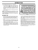
Страница 14: ... plug mower and leave undesirable clumps Allow grass to dry before mowing Always operate engine at full throttle when mow ing to assure better mowing performance and proper discharge of material Regulate ground speed by se lecting a low enough gear to give the mower cutting performance as well as the quality of cut desired When operating attachments select a ground speed that will suit the terrain...

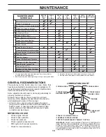
Страница 15: ...il without oil filter 1 2 maint_sch tractore ROS e BEFORE EACH USE EVERY 8 HOURS EVERY 25 HOURS EVERY 50 HOURS EVERY 100 HOURS EVERY SEASON BEFORE STORAGE Lubrication Chart Check Brake Operation Check Battery Level Check Tire Pressure Clean Battery and Terminals MAINTENANCE SCHEDULE Check for Loose Fasteners Check Replace Mower Blades Check Operator Presence ROS Systems Check Transaxle Cooling Che...

Страница 16: ...y The engine should not start unless the brake pedal is fully depressed and the attachment clutch control is in the disengaged position CHECK OPERATOR PRESENCE SYSTEM Whentheengineisrunning anyattemptbytheoperator to leave the seat without first setting the parking brake should shut off the engine When the engine is running and the attachment clutch is engaged any attempt by the operator to leave ...

Страница 17: ...install the drain tube onto the fitting Unlock drain valve by pushing inward and turning counterclockwise To open pull out on the drain valve After oil has drained completely close and lock the drain valve by pushing inward and turning clockwise until the pin is in the locked position as shown Remove the drain tube and replace the cap onto to the bottom fitting of the drain valve Refill engine wit...

Страница 18: ...th arrow pointing towards carburetor Be sure there are no fuel line leaks and clamps are properly positioned Immediately wipe up any spilled gasoline FIG 14 FUEL FILTER CLAMP CLAMP AIR FILTER Your engine will not run properly using a dirty air filter Service air cleaner more often under dusty conditions See Engine Manual ENGINE OIL FILTER Replace the engine oil filter every season or every other o...

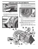
Страница 19: ...NSION ARMS A TO CHASSIS Position hole in arm over pin B on outside of tractor chassis and secure with retainer spring Repeat on opposite side of tractor TO REMOVE MOWER See Fig 15 Place attachment clutch in DISENGAGED position Lower attachment lift lever to its lowest position Roll belt off engine pulley M and belt keepers G Remove retainer spring K slide collar L off and push housing guide P out ...

Страница 20: ...nerspring K Install belt on engine pulley M in belt keepers G IMPORTANT CHECK BELT FOR PROPER ROUTING IN ALL MOWER PULLEY GROOVES Raise attachment lift lever to highest position If necessary adjust gauge wheels before operating mower as shown in the Operation section of this manual E F H J A B ATTACH FRONT LINK E Work from left side of trac tor Insert rod end of link assembly through front hole in...

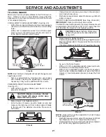
Страница 21: ...to raise LH side of mower NOTE Each full turn of adjustment nut will change mower height about 3 16 Test your adjustment by mowing some uncut grass and visually checking the appearance Readjust if necessary until you are satisfied with the results PRECISION SIDE TO SIDE ADJUSTMENT See Fig 21 With all tires properly inflated park tractor on level ground or driveway CAUTION Blades are sharp Protect ...

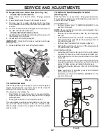
Страница 22: ...y grooves and inside all belt guides and keepers Install mower See TO INSTALL MOWER in this section of manual FIG 25 TO CHECK BRAKE If tractor requires more than five 5 feet to stop at highest speed in highest gear on a level dry concrete or paved surface then brake must be serviced You may also check brake by Park tractor on a level dry concrete or paved surface depress brake pedal all the way do...

Страница 23: ...wear eye protection when around batteries If your battery is too weak to start the engine it should be recharged See BATTERY in the Maintenance section of this manual If jumper cables are used for emergency starting follow this procedure IMPORTANT YOURTRACTORISEQUIPPEDWITHA12VOLT SYSTEM THE OTHER VEHICLE MUST ALSO BE A 12 VOLT SYSTEM DONOTUSEYOURTRACTORBATTERYTOSTART OTHER VEHICLES TO ATTACH JUMPE...

Страница 24: ...ood INTERLOCKS AND RELAYS Loose or damaged wiring may cause your tractor to run poorly stop running or prevent it from starting Check wiring See electrical wiring diagram in the Repair Parts section 03075 HOOD HEADLIGHT WIRE CONNECTOR FIG 31 TO REMOVE HOOD AND GRILL ASSEMBLY See Fig 31 Raise hood Unsnap headlight wire connector Stand in front of tractor Grasp hood at sides tilt toward engine and l...

Страница 25: ...FUELSYSTEMPARTSSUCH AS CARBURETOR FUEL FILTER FUEL HOSE OR TANK DURING STORAGE ALSO EXPERIENCE INDICATES THAT ALCOHOL BLENDED FUELS CALLED GASOHOL OR USING ETHANOLORMETHANOL CANATTRACTMOISTUREWHICH LEADSTOSEPARATIONANDFORMATIONOFACIDSDURING STORAGE ACIDIC GAS CAN DAMAGE THE FUEL SYSTEM OF AN ENGINE WHILE IN STORAGE Empty the fuel tank by starting the engine and let it run until the fuel lines and ...

Страница 26: ...Faulty ignition switch 7 Check replace ignition switch 8 Faulty solenoid or starter 8 Check replace solenoid or starter 9 Faulty operator presence switch es 9 Contact an authorized service center department Engine clicks but will not 1 Weak or dead battery 1 Recharge or replace battery start 2 Corroded battery terminals 2 Clean battery terminals 3 Loose or damaged wiring 3 Check all wiring 4 Fault...

Страница 27: ...el speed too fast 2 Shift to slower speed 3 Wet grass 3 Allow grass to dry before mowing 4 Mower deck not level 4 Level mower deck 5 Low uneven tire air pressure 5 Check tires for proper air pressure 6 Worn bent or loose blade 6 Replace sharpen blade Tighten blade bolt 7 Buildup of grass leaves and trash under mower 7 Clean underside of mower housing 8 Mower drive belt worn 8 Replace mower drive b...

Страница 28: ...ar 9 106268X Tire R T 18 x 9 5 8 Turf Saver 420531 Tire R T 18 x 9 5 8 Turf Saver LT 10 7152J Tube Rear 11 104757X421 Cap Axle Blk 1 50 x 1 00 144334 Sealant Tire 10 oz Tube 20 14 2 1 411658 Decal Warning 2 408834 Decal Eng H P 3 186164 Decal Hood LH 4 408794 Decal Side Panel Logo 5 411175 Decal Lwr Dash 6 170563 Decal Warning Keep Hand Away 7 413418 Decal Replacement Parts 9 172740 Decal Fender L...

Страница 29: ... HAVE THEIR OWN ELECTRICAL SOURCE BECAUSE OF THIS THE BRIGHTNESS OF THE LIGHTS WILL CHANGE WITH ENGINE SPEED AT IDLE THE LIGHTS WILL DIM AS THE ENGINE IS SPEEDED UP THE LIGHTS WILL BECOME THEIR BRIGHTEST WIRING INSULATED CLIPS NOTE IF WIRING INSULATED CLIPS WERE REMOVED FOR SERVICING OF UNIT THEY SHOULD BE REPLACED TO PROPERLY SECURE YOUR WIRING IGNITION SWITCH CIRCUIT POSITION OFF B A1 RUN OVERRI...

Страница 30: ... TRACTOR MODEL NUMBER PB19542LT 96042003401 PRODUCT NO 960 42 00 34 ELECTRICAL 30 33 34 22 79 21 41 42 26 43 27 40 71 16 87 25 T02S 90 28 55 With 12V Outlet Option 59 103 With Service Minder Option 46 46 94 92 29 93 2 ...

Страница 31: ...98885 Cable Ground 18 Rear Battery Blk 6 Ga 29 401545 Switch Seat 30 193350 Switch Ign 33 140401 Key Ign Molded Generic 34 110712X Switch Light Reset 40 401098 Harness Ign 41 17720408 Screw 1 4 20 unc x 1 2 42 131563 Cover Terminal Red 43 192507 Solenoid 55 17060512 Screw 5 16 18 x 3 4 71 400449 Harness Ign Chass 79 175242 Socket Asm Bulb Twistlock 87 197802 Switch Intrlck Clutch Cable Tx 90 40072...

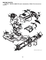
Страница 32: ...159 230 230 180 162 196 68 222 159 chassis tex_52 elite sv pro_r1 197 138 182 176 175 5 177 130 151 14 18 208 207 15 25 186 176 176 176 150 137 219 194 219 235 REPAIR PARTS TRACTOR MODEL NUMBER PB19542LT 96042003401 PRODUCT NO 960 42 00 34 CHASSIS ...

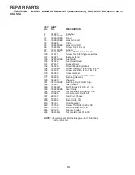
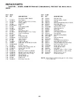
Страница 33: ...76 400776 Screw 10 24 x 5 8 Wshd Qdrx 177 195228 Bushing Steering 180 194260 Chassis 181 193102X428 Bushing Mtg Fender Crgo 182 193057 Dash Lower 183 74780520 Bolt Fin Hex 5 16 18 x 1 1 4 186 183829X428 Insert Grille 194 73900500 Nut Lock Hex Flange 5 16 18 196 410584 Console Asm Deck Lift 197 409167 Rod Pivot Chassis 207 183833 Bezel Grille RH 208 183832 Bezel Grille LH 219 195161 Stud Fastener 2...

Страница 34: ...34 REPAIR PARTS TRACTOR MODEL NUMBER PB19542LT 96042003401 PRODUCT NO 960 42 00 34 DRIVE ª ª ª ª ª ª ª ª ª ª ª ª DRIVE TEX ENDER ...

Страница 35: ... 158 194352 Keeper T A 159 76020412 Pin Cotter 1 8 x 3 4 160 169484 Retainer Clip 161 195403 Spring Return Clutch 162 195785 Spacer 165 196212 Busing Shaft Brake Hand Control 166 197290 Nut Push 625 167 405257 Latch Brake Parking 169 74490560 Bolt 5 16 18 x 3 75 172 197657 Strap Torque LH 174 197289 Nut Push 175 198981 Shaft Asm Shift 176 196214 Arm Clevis Rod Shift 178 197456 Spring Shift 184 198...

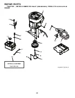
Страница 36: ...21 20 OPTIONAL EQUIPMENT Spark Arrester 29 18 15 37 28 engine bs 1cyl tex_4 12 42 85 9 90 84 45 1 81 82 69 2 79 97 96 REPAIR PARTS TRACTOR MODEL NUMBER PB19542LT 96042003401 PRODUCT NO 960 42 00 34 ENGINE ...

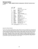
Страница 37: ...ing for individual gas engine models is labeled in accordance with SAE Society of Automotive Engi neers code J11940 Small Engine Power Torque Rating Procedure and rating performance has been obtained and corrected in accordance with SAE J1995 Revision 2002 5 Actual gross engine power will be lower and is affected by among other things ambient operating conditions and engine to engine variability G...

Страница 38: ...65 68 69 67 54 67 66 54 65 15 15 14 14 61 55 2 steering tex_15 lt 9 8 7 16 28 13 22 64 71 21 26 1 20 45 33 72 74 74 74 4 35 19 63 57 57 60 59 58 6 74 63 REPAIR PARTS TRACTOR MODEL NUMBER PB19542LT 96042003401 PRODUCT NO 960 42 00 34 STEERING ...

Страница 39: ... 188967 Washer Hardened 793 x 1 637 x 060 54 74760636 Bolt Hex HS 3 8 16 unc x 2 1 4 55 197636 Spacer Brace Axle 57 407465 Bracket Upstop 58 194747 Bolt Shoulder Sector Pivot CFM 59 194748 Washer Thrust Sector Steering 60 73971000 Nut Flange Lock 5 8 11 61 194740 Draglink LH 62 194741 Draglink RH 63 17000512 Screw 5 16 18 x 3 4 64 199849 Retainer Clip Spring Steering 65 194734 Brace Axle Front 66 ...

Страница 40: ...960 42 00 34 MOWER DECK 113 30 42 43 60 38 63 46 147 55 64 47 192 56 56 57 62 188 189 1 69 21 69 69 20 40 145 42_D_man Tex_LT_10_r3 21 21 24 25 26 27 29 23 189 188 144 36 113 113 40 57 19 19 6 6 68 30 30 32 38 195 122 123 195 31 33 34 59 15 14 13 11 8 16 70 7 7 37 67 152 ...

Страница 41: ...g Torsion Brake 43 197256 Spring Torsion Retainer 46 137729 Screw Thd Roll 1 4 20 x 5 8 47 197250 Bracket Clutch Cable 55 197249 Arm Idler 56 199092 Spacer Retainer 57 17000616 Screw Hexwsh Thd 3 8 16 x 1 59 141043 Guard Tuv Idler 94 60 197402 Arm Brake Mower 62 72110616 Bolt Rdhd Sqnk 3 8 16 unc x 2 63 199478 Arm Brake Mower 64 199918 Linkage Brake 67 198398X421 Handle Clutch Cable 68 197253 V Be...

Страница 42: ... x 3 4 w Sems 10 196977 Pan Seat 21 171852 Bolt Shoulder 5 16 18 37 73800500 Nut Lock 5 16 18 unc 40 197661 Handle Slide 41 198200 Spring Latch 43 74760612 Bolt 3 8 16 unc x 3 4 44 19133812 Washer 13 32 x 2 3 8 x 12 Ga REPAIR PARTS TRACTOR MODEL NUMBER PB19542LT 96042003401 PRODUCT NO 960 42 00 34 SEAT KEY PART NO NO DESCRIPTION KEY PART NO NO DESCRIPTION NOTE All component dimensions given in U S...

Страница 43: ... 89 19191912 Washer Clear Zinc 90 194208 Pin Cotter 5 16 Bow Tie Lock 91 195181 Link Lift Susp Mower Rear 97 17000612 Screw 3 8 16 x 75 Smgml Tap R Z 98 195270 Link Lift Susp Front Mower 100 73930600 Nut Lock 3 8 16 unc REPAIR PARTS TRACTOR MODEL NUMBER PB19542LT 96042003401 PRODUCT NO 960 42 00 34 MOWER LIFT KEY PART NO NO DESCRIPTION NOTE All component dimensions given in U S inches 1 inch 25 4 ...

Страница 44: ...44 SERVICE NOTES ...

Страница 45: ...45 SERVICE NOTES ...

Страница 46: ...46 SERVICE NOTES ...

Страница 47: ... never across the face Do not mow slopes greater than 15 degrees Make turns gradually to prevent tipping or loss of control Exercise extreme caution when changing direction on slopes 1 Fold this page along dotted line indicated above 2 Hold page before you so that its left edge is vertically parallel to a tree trunk or other upright structure 3 Sight across the fold in the direction of hill slope ...

Страница 48: ... for rental or commercial purposes is limited to 90 days from the date of original purchase 5 This Warranty applies only to products which have been properly assembled adjusted operated and maintained in ac cordance with the instructions furnished This Warranty does not apply to any product which has been subjected to altera tion misuse abuse improper assembly or installation delivery damage or to...

Отзывы: