background image

18

91.7.1 - GB/IE

InstructIons pErtaInInG to thE InstaLLEr

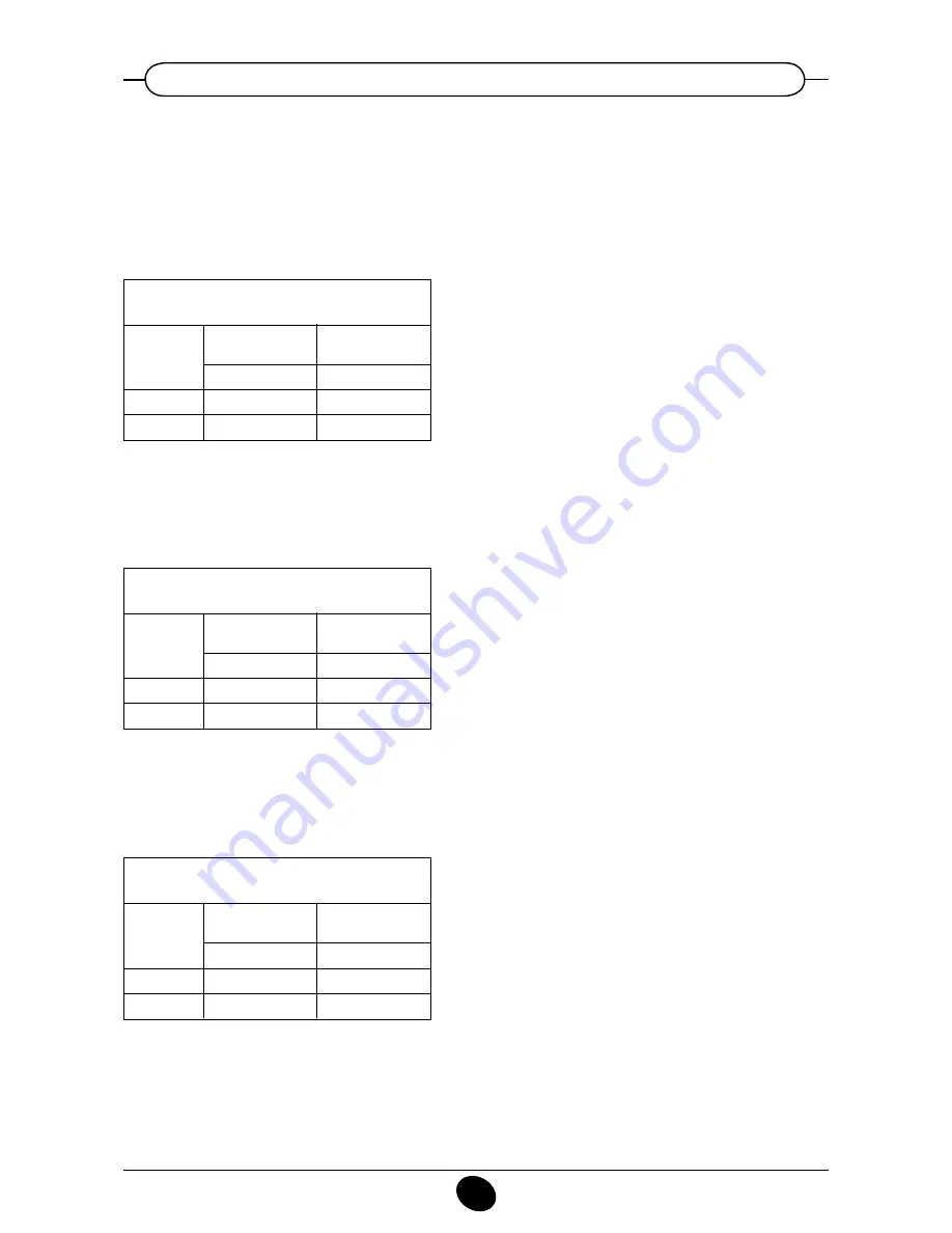
To ensure the correct rated heat output to the maximum and minimum heat input, it is necessary to update 
the speed (rpm) of the fan, it depends on the length of the flue (par. 12), in accordance with the installation of 
flue and air pipes as indicated in the tables below. The factory-set value is referred to the minimum length of 
flue pipe (0÷4 m for concentric, 0÷20 m for twin). To carry such updating, changing the speed of the fan (rpm) 
at the maximum and minimum heat input, refer to par. 16.

ConCentriC PiPe ø 80/125

(C13-C33-C43)

Pipes length

(m)

(*) 0 - 4

5 - 10

Parametres

H536-H613

Max heat output (rpm)

5500
5900

Parametres

H612

Min heat output (rpm)

1900
2100

wH 50

ConCentriC PiPe ø 80/125

(C13-C33-C43)

Pipes length

(m)

(*) 0 - 4

5 - 10

Parametres

H536-H613

Max heat output (rpm)

5600
6000

Parametres

H612

Min heat output (rpm)

1650
1800

wH 60

ConCentriC PiPe ø 80/125

(C13-C33-C43)

Pipes length

(m)

(*) 0 - 4

5 - 10

Parametres

H536-H613

Max heat output (rpm)

6000
6500

Parametres

H612

Min heat output (rpm)

1850
2100

wH 70

12.5 fan rpm updating depending on flue lengtH (e.g. figure 7)

(*) Default setting parameters

(*) Default setting parameters

(*) Default setting parameters

Содержание Sirius Three WH-50

Страница 1: ...Working towards a cleaner future Sirius WH 50 60 70 Wall Mounted Condensing Gas Boilers Installation Operation Maintenance Manual To be kept by the user October 2010 heating specialists ...

Страница 2: ...ler correctly and efficiently potterton COMMERCIAL boilers bear the CE mark in compliance with the basic requirements as laid down in the following Directives Gas Directive 90 396 CEE Performance Directive 92 42 CEE Electromagnetic Compatibility Directive 89 336 CEE Low Voltage Directive 73 23 CEE Do not leave any parts of the packaging plastic bags polystyrene etc within children s reach as they ...

Страница 3: ...10 Boiler installation 14 11 Boiler size 15 12 Installation of flue and air ducts 15 13 Hydraulic system 19 14 Connecting the mains supply 23 15 Gas valve adjustment 30 16 Setting the boiler parameters 32 17 Control and operation devices 33 18 Positioning of the ignition and flame sensing electrode 34 19 Check of combustion parameters 34 20 Activating the chimney sweep function 35 21 Annual servic...

Страница 4: ... and flushed out thoroughly to eliminate residual thread cutting swarf solder and solvents if any using suitable proprietary products To avoid damaging metal plastic and rubber parts use only neutral cleaners i e non acid and non alkaline The recommended products for cleaning are SENTINEL X300 or X400 and FERNOX heating circuit restore The use of this product must be strictly in accordance with th...

Страница 5: ...temperature Standby off Operation in manual mode at minimum tem perature Operation in manual mode at the maximum temperature set Operation in automatic mode Operation in central heating mode Operation in hot water mode 020503_1100 Figure 1 IMPORTANT The instructions contained in this manual relating to the operation of the hot water circuit are relevant only if the appliance is actually connected ...

Страница 6: ...to activate or inhibit this function which is identified by the appearance on the display of two black dashes under the symbol 4 Reset key In case of a fault referred to in point 3 7 Faults and resetting the boiler the boiler can be restarted by pressing this key for at least two seconds If this key is pressed with no fault present the display will show the message E153 and the same key has to be ...

Страница 7: ...igure 1 to set the central heating water temperature Press the keys to set the temperature required Press either of the keys 1 or 10 figure 1 to save and return to the main menu N B With the outdoor sensor connected the key 2 figure 1 can be used to shift the central heating cur ve Press the keys to decrease or increase the room temperature in the premises to be heated 3 3 setting the maximum cent...

Страница 8: ...ied by the factory the appliance is set up with the hot water function always enabled and the do mestic hot water programming function disabled The instructions for enabling this program are given in chapter 17 which is addressed specifically to installers parameter H91 If the program is enabled program lines from 31 to 36 must be set up as described in heading 3 5 1 3 6 setting the minimum centra...

Страница 9: ...ng End of third daily period of automatic central heating Start of first daily period of hot water production End of first daily period of hot water production Start of second daily period of hot water production End of second daily period of hot water production Start of third daily period of hot water production End of third daily period of hot water production Reset of daily central heating and...

Страница 10: ...igure 4 To reset press the reset button for at least two seconds 020503_0500 Figure 4 Figure 4 1 Fault warnings appear on the secondary display figure 1 b alternating with the time both of them flashing figure 4 1 It is not possible to reset malfunction warnings which appear on the secondary display as the cause of the alarm has first to be removed 3 8 fault warnings and resetting the boiler 0509_...

Страница 11: ...fault warnings table Action required Call the authorised service centre to check the wiring and or replace the sensor Call the authorised service centre to replace the sensor Call the authorised service centre to replace the sensor Press the reset key for about 2 seconds if this device is triggered repeatedly call the authorised service centre Call the authorised service centre to check the flame ...

Страница 12: ...ic management of the boilers includes a frost protection function which operates the burner to reach a heating flow temperature of 30 C when the system heating flow temperature drops below 5 C The frost protection function is enabled if electrical supply to the boiler is on the gas service cock is open the system pressure is as required the boiler is not isolated To maintain efficient and safe ope...

Страница 13: ...ensure correct operation of the appliance and avoid invalidating the warranty observe the following precautions 1 Hot water circuit If the water hardness is greater than 20 F 1 F 10 mg calcium carbonate per litre of water a polyphosphate or comparable treatment system responding to current regulations must be used 2 Heating circuit 2 1 New system Before proceeding with installation of the boiler t...

Страница 14: ...bber parts use only neutral cleaners i e non acid and non alkaline such us SENTINEL X100 and FERNOX heating circuit protective To use this product proceeding strictly in accordance with the maker s directions Remember that the presence of foreign matter in the heating system can adversely affect the operation of the boiler e g overheating and noisy operation of the heat exchanger Dose with inhibit...

Страница 15: ...boiler thanks to the fittings and fixtures supplied de scribed below The boiler is especially designed for connection to an exhaust flue air ducting with either concentric vertical or horizontal terminal Where exhaust and intake flues not supplied by potterton COMMER CIAL have been installed these must be certified for the type of use and must have a maximum pressure drop of 100 Pa for the complet...

Страница 16: ...minal is below 2m then a terminal gaurd is required Ensure a minimum downward slope of 3 towards the boiler A 87 bend reduces the total flue length by 1 metre A 45 bend reduces the total flue length by 0 5 metre 1 2 3 4 WH50 Ø80 125 9 m 8 m 7 m 6 m WH60 Ø80 125 9 m 8 m 7 m 6 m WH70 Ø80 125 9 m 8 m 7 m 6 m HORIZONTAL CONCENTRIC FLUES Boiler Flue Size Number of Bends 90 1 2 3 4 WH50 Ø80 125 9 m 8 m ...

Страница 17: ...be carried out both on a flat or pitched roof by fitting a terminal an appropriate weathering tile and sleeve supplementary fittings supplied as options L max 10 m L max 10 m L max 9 m L max 8 m 0310_0107 L refer also the table 0602_0702 12 1 horizontal flue terminal Ø 80 125 installation options L refer to table Figure 8 990519_0400 Concentric outlet ...

Страница 18: ... at the maximum and minimum heat input refer to par 16 concentric PIPE ø 80 125 C13 C33 C43 Pipes length m 0 4 5 10 Parametres H536 H613 Max heat output rpm 5500 5900 Parametres H612 Min heat output rpm 1900 2100 wh 50 concentric PIPE ø 80 125 C13 C33 C43 Pipes length m 0 4 5 10 Parametres H536 H613 Max heat output rpm 5600 6000 Parametres H612 Min heat output rpm 1650 1800 wh 60 concentric PIPE ø...

Страница 19: ...ation Details Pumped heating circuits with remote control QAA73 or Room Thermostat including hot water tank without and with primary loop 13 1 Hydraulic system 1 Figure 9b 0602_0703 CG1756 with low loss header and primary loop Figure 9a 0602_0704 CG1782 without low loss header optional extra optional extra ...

Страница 20: ...turn valve Not supplied Applications pumps sensor remote control have to be connected to terminal as follows see also section 14 WITH QAA73 WITH REMOTE CONTROL ROOM THERMOSTAT APPLICATION TERMINAL BOARD TERMINAL BOARD PRIMARY PUMP PLP only for figure 9b M1 A B M1 A B DHW PUMP PDHW M3 13 14 M3 13 14 HEATING PUMP P1 M3 11 12 M3 11 12 DHW SENSOR TS M2 7 8 M2 7 8 REMOTE CONTROL QAA73 M2 1 2 NO ROOM TH...

Страница 21: ...73 B1 Room Thermostat B9 Temperature Sensor QAC34 supplied with the gas boiler Zone Controller Clip in AGU2 500 FS Flow Sensor QAD36 supplied with AGU2 500 P1 Heating Pump P DHW Hot Water pump PLP Primary Pump 3WV 3 way Valve power open power close Available Optional Extra Pumps Not Supplied Isolating Valve Not Supplied Installer Wiring Hot Water Cylinder Not Supplied Low Loss Header Not Supplied ...

Страница 22: ...minal as follows see also section 14 Parameter changes requires see also section 16 PCB Description Setting Parameter PARAMETER H552 Hydraulic system H552 50 H553 KonfigHKS H553 12 H615 KonfigAusgang H615 9 H632 Wanfo Q8 H632 00001111 13 3 heat EXCHANGER PRESSURE DROP kPa Lit sec kPa Lit sec kPa Lit sec kPa Lit sec WH50 70 61 0 98 31 38 0 72 11 77 0 54 10 79 0 36 WH60 61 78 1 19 30 40 0 88 17 65 0...

Страница 23: ... correct Use a double pole switch isolator with a contact separation of at least 3mm in both poles In case you replace the power supply cable fit a HAR H05 VV F 3x0 75mm2 cable with an 8mm diameter maximum outer sheath The fuse a fast acting type rated 2A is incorporated into the power supply terminals remove the black fuse holder to enable inspection and or replacement IMPORTANT Check that the ov...

Страница 24: ...nd rating of the pump by referring to its hydraulic resistance table Terminals M3 11 12 connection for heating pump P1 Terminals M3 13 14 connection for hot water tank pump PDHW The electrical specifications of the pump must be as follows 230 V AC 50 Hz 1 A max cos f 0 8 If the specifications of the installed pump are different a relay must be wired between the boiler control circuit board and the...

Страница 25: ...ccessory The sensing element of the NTC device must be located in the recess provided on the storage tank figure 13 The temperature and on off programming of the domestic hot water supply are selected directly from the boiler control panel as described in this manual under the user instruction headings 14 2 Connecting the hot water tank sensor Figure 13 0602_0707 CG1764 safety contact room thermos...

Страница 26: ...ere is no voltage across the ends of the two thermostat connection wires Terminals 5 6 external safety contact low voltage Terminals 7 8 connection of SIEMENS model QAC34 outdoor temperature sensor supplied with the gas boiler Read the instructions supplied with this accessory for correct installation procedures Terminals 9 10 connection of hot water temperature sensor supplied as optional extra f...

Страница 27: ...t of the other zones can be set directly on the boiler control panel See the instructions provided with the QAA73 room temperature regulator for the user parameter programming procedure IMPORTANT For systems divided into zones parameter 80 HC2 curve which can be set on the QAA73 temperature regulator must be set as _ _ _ not active QAA73 parameters which can be set by the installation engineer ser...

Страница 28: ...tion of the fault see Fault warning tables on paragraph 3 9 Line no 70 72 74 75 77 78 79 80 90 91 Default value 15 85 Light On HC1 On 0 0 10 24 h day Range 2 5 40 25 85 Light Heavy on HC1 on HC2 on HC1 HC2 nil On off 0 360 min 0 360 min 2 5 40 not active 10 or 35 58 24 h day TSP HC 1h TSP HC TSP DHW Parameter HC1 curve Selection of central heating circuit temperature curve kt HC1 max output Centra...

Страница 29: ...h can be set by the installation engineer service See graph 4 for selecting the curve referred to a room temperature of 20 C The curve is shifted automatically on the basis of the room temperature set using the QAA73 climate con trol If the system is divided into zones the temperature curve kt relating to the part of the system not control led by the QAA73 must be selected by setting parameter H53...

Страница 30: ...re connection point for measurement of the OFFSET Pl Air signal input from fan V Gas flow adjuster screw max fire K OFFSET adjuster screw min fire 15 gas valve adjustment Carry out the following ope rations in the given sequence 1 Calibration of the maximum heat output Check that the CO2 measured on the flue with the boiler operating at the maximum heat output is the same as that shown in table 1 ...

Страница 31: ... 5 15 Gas consumption at 15 C 1013 mbar WH 50 WH 60 WH 70 gas G31 3P 37 mbar PCI MJ Kg NET 46 34 46 34 46 34 Consumption at max heat output Kg h 3 60 4 40 5 20 Consumption at min heat output Kg h 1 16 1 24 1 55 Gas nozzle mm 8 5 15 G20 2H 20 mbar G31 3P 37 mbar CO2 max heat output 8 7 10 CO2 min heat output 8 4 9 8 IMPORTANT in the case of conversion from natural gas to propane LPG the following o...

Страница 32: ...ne corresponding to the circuit of the low temperature zone if the SIEMENS AGU2 500 accessory is used Automatic Summer Winter switching temperature C Selection of temperature curve of central heating circuit HC1 see Graph 1 Selection of temperature curve of central heating circuit HC2 see Graph 1 Maximum speed at maximum output in heating mode rpm maximum speed limitation Setting value of required...

Страница 33: ...failure or incomplete interlighting of the main burner Under such conditions the boiler is locked out You must press the reset button on the boiler to restore the normal operating conditions Supplementary pump overrun After the burner has switched off due to a room thermostat intervention the preset pump overrun of the pump lasts 10 minutes when the boiler is in the central heating mode Frost prot...

Страница 34: ...test points is connected to the exhaust flue duct to allow measurements of the combustion products and efficiency The second test point is connected to the comburant air inlet duct to check possible combustion products circulation in case of coaxial ducts The exhaust flue duct test point allows measurements of the following combustion products temperature concentration of oxygen O2 or alternativel...

Страница 35: ...tons to exit the function Figure 19 To ensure the boiler operates at peak efficiency the following checks must be performed every year Check on the appearance and tightness of the gas and combustion circuit gaskets Check on the condition and position of the ignition and flame sensing electrodes see section 18 Check on the condition of the burner and its fixing to the aluminium flange Check for any...

Страница 36: ...on condensate 4 Central heating ntc sensor 5 105 C overheat thermostat 6 Gas valve 7 Heat exchanger 8 Flame detector electrode ionisation probe 9 Main burner 10 Ignition electrode 11 Air gas mixture header 12 Mixer with venturi 13 Injector 14 Fan 15 Flue thermostat 16 Flue spigot 17 Automatic air vent 18 Flue joint 19 Hydraulic pressure sensor 20 Pressure gas switch 22 boiler schematic 0512_0406 C...

Страница 37: ...37 912 272 1 GB IE instructions pertaining to the installer 23 illustrated wiring diagram 0602_0709 CG1745 br brown bk black b blue r red g green g y green yellow w white cables colours ...

Страница 38: ... duct diameter mm 125 125 125 Twin pipe flue duct diameter mm 80 80 80 Twin pipe air duct diameter mm 80 80 80 Max flue mass flow rate kg s 0 022 0 027 0 032 Min flue mass flow rate kg s 0 007 0 008 0 010 Max flue temperature C 74 78 75 NOx class 5 5 5 NOx mg kWh 38 4 33 9 37 7 Type of gas used G20 G20 G20 G31 G31 G31 Natural gas pressure 2H mbar 20 20 20 Propane gas pressure 3P mbar 37 37 37 Gas ...

Страница 39: ...39 912 272 1 GB IE instructions pertaining to the installer ...

Страница 40: ...LL Tel 0844 871 1540 Applications Installations Our experienced technical support team are available to offer advice on any aspect of heating system design and boiler installation Please contact 0845 070 1057 Commercial service offices Our service organisation covers the whole of the UK to look after your needs for all Potterton Commercial products Our service office offers a wide range of special...

Отзывы: