Potterton Gold 11 kW Скачать руководство пользователя страница 9

9

ALL WIRING MUST BE CARRIED OUT IN ACCORDANCE WITH CURRENT IEE WIRING REGULATIONS.

The POTTERTON GOLD boiler must be installed by a qualified competent tradesman in accordance 
with supplied instructions and drawings to ensure correct operation.  

Check the main incoming supply to the property to ensure there is sufficient current and voltage 
for the size of the boiler or boilers to be installed. Remember to also take account of the supply 
requirements for the rest of the property. Ensure the correct cable size is used to feed the boiler 
(refer to IEE wiring regulations).

A double pole RCD with a trip level sensitivity of 30mA and capable of breaking the full load current 
to BS EN 61008:1994, must be used.

In order to provide a means of isolation, the boiler must be connected to the supply through a double 
pole linked switch with a minimum contact gap of 3mm in all poles. The RCD is suitable for this 
requirement if it is mounted in close proximity to the boiler.

A correctly rated MCB must be used in the supply, see Technical Specifications (page 3). An additional 
3A supply is required for the controls etc.  NOTE, a blank must be fitted between each MCB to provide 
ventilation, check with the MCB manufacturer/supplier.

NOTE: The high current mains supply MUST NOT be routed through the programmer, controls etc.  
Follow the wiring diagrams.  Use a standard programmer, room thermostat, etc. The high current 
switching is carried out inside the boiler, only standard switched live (low current) control signals 
are supplied by the programmer etc.

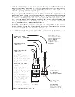
Electrical Connections

Access can be gained to the electrical connections by removing the top front panel.

CONN  5:  MAIN  POWER.  Main  power-supply  cables.  Connect  the  power  cables  from  the  power 

1. 

“supply”  (CONN 5) terminals on the PCB assembly in the boiler directly to the isolation switch, live, 
neutral and earth. Use the correct rated cable. Do not connect the power through the programmer, 
thermostats etc. The main power PCB terminals in the boiler are suitable for cables up to 10mm

2

.  

NOTE: THESE CONNECTIONS MUST BE TIGHT. LOOSE CONNECTIONS WILL CAUSE BURNING AT 
CONN 5 CONNECTOR, THIS IS NOT COVERED BY THE WARRANTY.

CONN 1 pins 2 & 3:  CONTROL SIGNAL. Connect switched live to ‘R’ and neutral to ‘N’ on the 

2. 

control terminal block in the boiler to the switched live and neutral from the programmer control 
circuit. A neutral must be connected, as this control signal is optically isolated from the main 
supply in the boiler and will not run without a neutral. Do not connect any wires to the terminal 
marked N/C.

CONN 1 pins 4, 5 & 6: PUMP CONNECTIONS. The supply to the pump must be connected to the 

3. 

‘PUMP’ terminal on the control terminal block in the boiler. This supply is fused in the boiler at 
2A.

Cable access is made from either the right or left hand side via the x3 knockouts provided (x1 

4. 

25mm for power and x2 20mm for pump and thermostat cables). Having decided which side to 
route the cables, remove x3 knockouts only (This can be achieved with a small tap from a ball 
nose hammer, then twisting the knockout untill it is removed. Note: Take care not to damage the 
casing, ensure the metal discs are retrieved and no sharp edges are present. The cables should 
be installed using a cable compression gland (not supplied).

 INSTALLATION - ELECTRICAL REQUIREMENTS

x3 KNOCKOUTS
LEFT HAND SIDE

X3 KNOCKOUTS 
RIGHT HAND SIDE

FIGURE FIVE: CASE KNOCKOUTS

FIGURE SIX: TWISTING KNOCKOUT

Содержание Gold 11 kW

Страница 1: ...N AND SERVICING INSTRUCTIONS PACK CONTENTS The POTTERTON GOLD electric boiler Guarantee registration card Fitting user instructions IMPORTANT PLEASE READ AND UNDERSTAND THESE INSTRUCTIONS BEFORE COMMENCING INSTALLATION PLEASE LEAVE THIS MANUAL WITH THE CUSTOMER FOR FUTURE REFERENCE ...

Страница 2: ... AND THESE INSTRUCTIONS LEFT WITH THEM FOR FUTURE REFERENCE THIS APPLIANCE IS NOT INTENDED FOR USE BY PERSONS INCLUDING CHILDREN WITH REDUCED PHYSICAL SENSORY OR MENTAL CAPABILITIES OR LACK OF EXPERIENCE AND KNOWLEDGE UNLESS THEY HAVE BEEN GIVEN SUPERVISION OR INSTRUCTION CONCERNING USE OF THE APPLIANCE BY A PERSON RESPONSIBLE FOR THEIR SAFETY INTRODUCTION FIGURE ONE MAIN COMPONENTS OF POTTERTON G...

Страница 3: ... 1050 x 90 x 90mm 94022108 U floor 4kW 3 5kW 11 900Btu 4kW 13 600Btu 1050 x 90 x 90mm 94022004 Rad 6kW 5kW 17 000Btu 6kW 20 400Btu 1050 x 90 x 90mm 94022104 U floor 6kW 5kW 17 000Btu 6kW 20 400Btu 1050 x 90 x 90mm 94022005 Rad 9kW 7 5kW 25 600Btu 9kW 30 700Btu 1050 x 90 x 90mm 94022105 U floor 9kW 7 5kW 25 600Btu 9kW 30 700Btu 1050 x 90 x 90mm 94022006 Rad 11kW 9kW 30 700Btu 11kW 37 500Btu 1050 x ...

Страница 4: ... and not subjected to extremes of temperature Note Before connecting the pipework ensure the rubber seal at the top of the boiler is firmly in place check it has not become loose in transit The warranty will be invalid if water leaks into the boiler INSTALLATION GENERAL TOP HAUT ALTO OBEN WARN ING Before obtaining access to terminals all supply circuits must be disconnected Do not solder directly ...

Страница 5: ...oiler tails Push on or compression fittings are suitable for connecting directly onto the boiler tails Fit a 22mm elbow to the top of the boiler and after 100 150mm of horizontal pipework fit an automatic air vent or connect the expansion pipework on open vented systems to provide a route for air to vent DO NOT FIT THE AAV DIRECTLY ABOVE THE BOILER The electric boiler is suitable for operation in ...

Страница 6: ...s at the bottom Tee in the flows together increasing in pipe size at each boiler to ensure full flow to each boiler E g for 3 x 12kW boilers first boiler use a 22mm elbow to the second boiler Second boiler tee 22mm in from first boiler 22mm branch to second boiler 28mm to third boiler Third boiler tee 28mm in from second boiler 22mm branch to third boiler 35mm away to heating circuit Repeat for th...

Страница 7: ...MP ISOLATING VALVE 150mm MINIMUM 2 METRES MINIMUM ELECTRIC BOILER AUTOMATIC PRESSURE BYPASS VALVE FLOW RETURN DRAIN VALVE ALTERNATIVE BY PASS ARRANGEMENT USING THE BATHROOM RADIATOR FITTED WITH TWO LOCKSHIELD VALVES OPEN VENTED SYSTEMS MUST HAVE A MINIMUM HEAD OF 1 5 METRES AND MAXIMUM HEAD OF 30 METRES ...

Страница 8: ...2 x 12kW boilers 28mm pipework flow and return is required A bypass must be fitted Preference should be made for a 600 x 600 radiator FIGURE FOUR THREE BOILER PLUMBING SCHEMATIC AUTOMATIC AIR VENT EXPANSION SAFETY RELIEF SYSTEM SERVICE VALVE PUMP ELECTRIC BOILER FLOW DRAIN VALVE ELECTRIC BOILER ELECTRIC BOILER 35mm PIPE FLOW 36 LITRE MIN 28mm PIPE FLOW 24 LITRE MIN 22mm PIPE FLOW 12 LITRE MIN 35mm...

Страница 9: ...ical connections by removing the top front panel CONN 5 MAIN POWER Main power supply cables Connect the power cables from the power 1 supply CONN 5 terminals on the PCB assembly in the boiler directly to the isolation switch live neutral and earth Use the correct rated cable Do not connect the power through the programmer thermostats etc The main power PCB terminals in the boiler are suitable for ...

Страница 10: ...s Loose connections can cause burning at the connectors and will invalidate the warranty The control RUN signal is optically isolated from the main boiler supply to enable different phases to be used between boilers The control signal required to operate the boiler is 220V 240V at a very low current typically 10mA Warning this appliance must be earthed All exposed pipework must be earthed in accor...

Страница 11: ...R N L MAINS SUPPLY DOUBLE POLE RCD OR DOUBLE POLE ISOLATION LOCAL TO BOILER DOUBLE POLE ISOLATION SWITCH OR DOUBLE POLE RCD 3A FUSED SPUR OR MCB HEAT RESISTANT CABLE DEMAND SIGNAL FROM CONTROLS PROGRAMMER ETC SEE TYPICAL WIRING DIAGRAMS TO CONTROLS PROGRAMMER ETC EARTH BONDING TO BE PERFORMED IN ACCORDANCE WITH BS7671 BOILER SUPPLY MCB L N ...

Страница 12: ...WHEN TIGHTENING SCREWS ENSURE SCREWS ARE TIGHT LOOSE CABLE CONNECTIONS CAN CAUSE BURNING AT THE CONNECTOR SUPPLY CONN 5 CONN 1 FS 1 2A 240V 5 X 20mm REMOVE TOP COVER ONLY TO GAIN ACCESS TO THE CONNECTIONS ON THE PRINTED CIRCUIT BOARD INSIDE THE BOILER HOUSING LIVE EARTH NEUTRAL LIVE EARTH NEUTRAL RUN NEUTRAL N L CONTROL PUMP CONTROL PUMP NC N R E N L NC N R E N L CASE EARTH 2 2 2 2 ...

Страница 13: ...G DIAGRAM ROOM STAT CYLINDER STAT BLUE GRN YLW BROWN GREY ORANGE 2 1 3 1 C 2 E N L N RUN TO BOILER L N CH ON HW ON CH OFF HW OFF FROM 3A FUSED SPUR OR MCB 1 2 3 4 5 6 7 8 9 10 TIME CONTROLLER BLUE GRN YLW BROWN GREY ORANGE 2 PORT VALVES ...

Страница 14: ...Y ORANGE 2 1 3 C 1 2 E N L N RUN TO BOILER L N CH ON HW ON CH OFF HW OFF FROM 3A FUSED SPUR OR MCB TIME CONTROLLER FIGURE ELEVEN TYPICAL Y PLAN WIRING DIAGRAM 1 2 3 4 5 6 7 8 9 10 1 2 3 4 5 6 7 8 9 10 MID POSITION VALVE E N L N RUN TO BOILER FROM 3A FUSED SPUR OR MCB PROGRAMMABLE ROOM THERMOSTAT A B C ...

Страница 15: ... room thermostats in the main zone and TRV s in all other zones 6 Cylinder thermostat and zone valve to control stored hot water Non electric hot water controllers do not comply 7 Timed controller for heating and hot water must be provided 8 A minimum of 2 zones for heating floor spaces greater than 150m2 9 Boiler management control systems meeting specific zoning timing and temperature requiremen...

Страница 16: ...he system and set the pump to maximum 4 Switch on the control supply only 3 amp or 6 amp MCB 5 With the programmer and room thermostat on check the pump is running and water is flowing 6 Ensure the whole system valves etc are operating correctly Continue to run the pump for some time to purge any air Don t forget to bleed the pump Switch off the main supply RCD and MCB s Ensure it is all safe befo...

Страница 17: ...e full system operates correctly If at any time the temperature difference between the 4 boiler return and flow is greater that 140 C then there is a flow restriction problem and must be rectified immediately Set pump speed to give 5 100 C differential between return and flow on the boiler when operating at maximum power output The pump is operated from the boiler control It should be connected to...

Страница 18: ... RED ALARM LED FLASHING IS TEMP SWITCH OPEN I E FAULTY OR BOILER OVER TEMP DO BOTH THERMISTOR BEADS READ SAME VALUE I E TEMPERATURE CONTINUE CHECK FOR A FURTHER 2 MINUTES SWITCH OFF PRE HEAT POWER UP AND MODULATE BOILER RUN TO OFF BOILER POWERS DOWN IS WATER IN BOILER BELOW 70ºC 75ºC KEEP PUMP RUNNING OR PUMP ON ALARM LED FLASHING NO WATER OR INSUFFICIENT WATER FLOW PUMP OFF YES NO NO YES NO YES ...

Страница 19: ... IS CHECKED ANNUALLY Checks must include the electrical connections and inhibitor concentration Before any servicing or maintenance is carried out on the system ensure that the electrical supply has been disconnected first Care must also be taken as the water may be scalding hot and at a high pressure Check the main electrical power connections are tight Loose connections can cause a burning at th...

Страница 20: ...he main power cable to Conn5 6 Remove the 4 screws identified by the black triangles see figure sixteen below 7 Carefully remove the PCB assembly from the pipework This may be stiff and gentle prising at 8 the top may be required Replacing the Main Power PCB Ensure heat sink compound is used on the heat sinks 1 Identify and plug the power connectors onto the elements colour for colour as it is eas...

Страница 21: ...apacitor between the R run and N neutral terminals on the control connector to prevent the boiler continuing to run when the cylinder and the room thermostats are satisfied This is due to a leakage current from some manufacturers 3 port valves The capacitor required is 0 47 micro farads suitable for 275 volts AC X2 style These capacitors are available from Potterton Gold 95612708 FAULT FINDING ALA...

Страница 22: ...A ULT FINDING SECTION NO YES IS THE ALARM LED ILLUMINATED GO TO ALARM FAULT FINDING SECTION YES NO IS THE SUPPLY LED ILLUMINATED GO TO SUPPLY LED OFF FAULT FINDING SECTION NO YES THE BOILER IS NOT OPERATING PLEASE CHECK THE FOLLOWING BEFORE GOING THROUGH THE FAULT FINDING CHART CHECK INSTALLATION IS CORRECT ALL ISOLATING VALVES ARE OPEN THE SYSTEM IS FULL OF WATER PRESSURISED AND PURGED OF AIR THE...

Страница 23: ...WITH ALARM TO ALLOW PUMP TO COOL SYSTEM BEFORE RESETING NO YES IS CONN 3 OPEN CIRCUIT IS THE BOILER HOT CHANGE CONTROL PCB IS THERE 8V DC ON C1 MAIN PCB REPLACE THE MAIN POWER PCB REPLACE THE CONTROL PCB NO YES IS THERE 230V ON TVR 1 MAIN PCB CHECK FOR SHORT CIRCUITS ON WIRING TO THE PUMP IF OK REPLACE FS1 FUSE T 2A 240V 20 x 5mm NO YES IS THE MAIN SUPPLY AVAILABLE CHECK 240V IS SUPPLIED TO THE MA...

Страница 24: ...IR IN THE SYSTEM NO YES ALARM TRIPS AFTER A FEW MINUTES OF OPERATION FIGURE TWENTY TWO ALARM FOUR YES TRIPPING DAILY CHECK FLOW AND PRESSURE CHECK FOR TEMPORARY RESTRICTIONS IN FLOW CHECK CONNECTIONS ON THERMOSTATIC SWITCH CONN3 CHANGE CONTROL PCB NO OCCASIONAL TRIPPING CHECK FLOW AND PRESSURE CHECK FOR TEMPORARY RESTRICTIONS IN FLOW CHECK CONNECTIONS ON THERMOSTATIC SWITCH CONN3 RESET FIGURE TWEN...

Страница 25: ...HE CONTROL CONNECTOR CHANGE THE CONTROL PCB NO YES IS THERE 230V BETWEEN R AND N CONTROL CHECK THE WIRING TO THE BOILER NO YES IS THE 240V DEMAND AVAILABLE CHECK AND SET THE PROGRAMMER AND THERMOSTATS ON NO YES CALL LED NOT FLASHING NO DOES THE MAIN RCD TRIP CHANGE CONTROL PCB YES CALL LED NOT STEADY AFTER 3 MINUTES CHECK THE INSULATION ON THE ELEMENTS ...

Страница 26: ...ss X2 For 2 boilers use Part Number 94970057 For 3 boilers use Part Number 94970058 PUMP RELAY CONTROL FOR POTTERTON GOLD ELECTRIC BOILERS PERMANENT LIVE SUPPLY 240V NEUTRAL EARTH RL 1 N O CONTACT RL 3 N O CONTACT RL 2 N O CONTACT PUMP LIVE PUMP NEUTRAL EARTH FIGURE TWENTY FIVE PUMP RELAY CONTROL FOR ELECTRIC BOILERS ISOLATION RELAY COIL RL1 240V N L 4 7uF CAPACITOR 240V AC ISOLATION RELAY COIL RL...

Страница 27: ...ll restart Electric showers are normally run for short periods at a time and therefore shutting down the heating during these times should not cause any discomfort Note this is only required if there is doubt with regard to supply limitations and an electric shower that heats the water at the same time as the electric boiler is used It is not required with power showers which only pump the water A...

Страница 28: ...antee in no way affects the statutory rights of the consumer GUARANTEE PARTS LIST Part Number Description 95615047 Main Power PCB Assembly 95615046 Control PCB Assembly Radiator Version 95615048 Control PCB Assembly Underfloor Version 95612709 Fuse T 2A 240V 95613628 Temperature Switch Cable Assembly 95612706 Thermistor Assembly 95612708 Capacitor 0 4uF ENVIRONMENTAL INFORMATION POTTERTON GOLD pro...

Отзывы: