


17
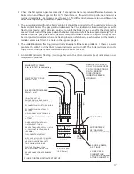
FIGURE THIRTEEN: INITIAL TEST SET UP
NO CONNECTION
PUMP SUPPLY CABLE
0.5mm - 1mm
MAINS SUPPLY CABLE
Refer to BS7671 for cable sizing
BOILER CONTROL CABLE
0.5mm - 1mm
SUPPORT BACK
OF PCB WHEN
TIGHTENING SCREWS
ENSURE SCREWS
ARE TIGHT.
LOOSE CABLE
CONNECTIONS
CAN CAUSE BURNING
AT THE CONNECTOR
SUPPLY
CONN 5
CONN 1
FS 1 2A 240V
(5 X 20mm)
REMOVE TOP COVER
ONLY TO GAIN ACCESS
TO THE CONNECTIONS
ON THE PRINTED
CIRCUIT BOARD
INSIDE THE BOILER
HOUSING
LIVE
EARTH
NEUTRAL
LIVE
EARTH NEUTRAL
RUN
NEUTRAL
N
L
CONTROL
PUMP
CONTROL
PUMP
NC N R E N L
NC N R E N L
CASE EARTH
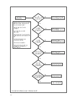
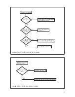
INITIAL TEST SET UP
REMOVE PUMP LIVE AND PUMP
NEUTRAL WIRES FROM CONN1 BLOCK.
RECONNECT PUMP LIVE TO RUN WIRE.
RECONNECT PUMP NEUTRAL TO
NEUTRAL.
UNPLUG CONN1 BLOCK FROM PCB.
ENSURE IT IS SAFE BEFORE CARRYING
OUT TEST.
POWER UP SYSTEM WITH ALL
CONTROLS SET TO RUN.
ENSURE THE BOILER SUPPLY LIGHT IS
ON, CALL LIGHT IS OFF AND PUMP
IS RUNNING.
THIS COMPLETES THE TEST.
SWITCH OFF ALL POWER TO BOILER
AND RECONNECT PUMP NEUTRAL
AND PUMP LIVE WIRES BACK TO
THEIR ORIGINAL POSITIONS.
PLUG THE TERMINAL BLOCK
BACK INTO CONN1 ON THE PCB.
ENSURE CONNECTION SCREWS ARE
TIGHT
2
2
2
2
Check the full system operates correctly. If at any time the temperature difference between the
4.
boiler return and flow is greater that 14
0
C, then there is a flow restriction problem, and must be
rectified immediately. Set pump speed to give 5-10
0
C differential between return and flow on the
boiler when operating at maximum power output.
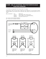
The pump is operated from the boiler control. It should be connected to the pump terminals on the
5.
boiler control board. The pump will run whenever the CALL indicator is illuminated (green) either
flashing or steady, and it will also continue to run if the boiler is hot, even after the demand has
ceased. It will turn off the pump when the boiler temperature falls below approximately 75
0
C. It
will also turn the pump back on if the water temperature rises above 75
0
C again. A bypass must
be incorporated in systems where the heating load can shut down, i.e. when valves or thermostatic
radiator valves are fitted. See note on the bypass (page 5).
The
6.
ALARM indicator flashing (red) will only illuminate if there is a problem. If there is a water
problem the HEAT and the CALL (green) indicators will turn off. The boiler will remain in this
tripped state until the fault is corrected and the boiler is re-set.
An ALARM indicator flashing (red) together with the CALL indicator (red) indicates an over
7.
temperature problem.