Part 3
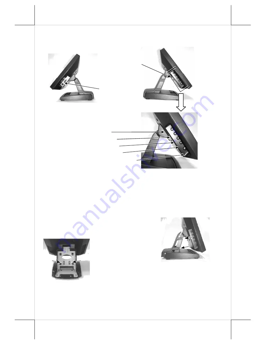
Control button area
VGA Connector and
DC jack.
NXT button
“+” button
OSD button
“-“ button
Power switch
C. SIDE VIEW (LM-2210)
D. POWEPOWER LED INDICATION
•
Green: standby (no signal)
•
Blue: operating
Before routing the cable, please release the hooks
Of stand’s back cover as arrowed in the right
picture
.
For cable routing in mini slim base,
please refer to the picture
at left. There are 2 cable
tie holder slits on the
metal bracket for the
trunk as arrowed in the picture. Hold all the external
cables with a cable tie through the right cable tie holder
slit and leave the cables to the left holder slit. Have all
cables to pass through the oval hole on the trunk to come out of the front side
of trunk. Connect all the cable ends to main unit. Be sure not to damage any
cable during this operation.
CABLE ROUTING IN BASE (LM-2210)


