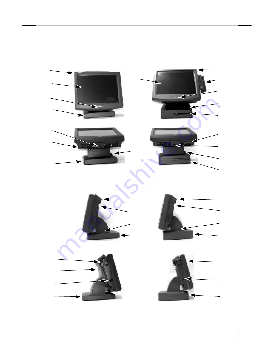
background image


Part 3 

INTRODUCTION 

PRODUCT PICTURES 

Front Views 


Side Views 


TP-5815 Pro / TP-8000


TP-5915 Pro / TP-8200


TP-5815 Pro / TP-8000


TP-5915 Pro / TP-8200


11


11


12


1


12


12


10


10


7


5


13


13


5


7


1


TP-5815 Pro / TP-8000


7


3


4


1


1


TP-5915 Pro / TP-8200


4


5


6


9


8


8


9


10


10


7


5


2


2


TP-5815 Pro / TP-8000


TP-5915 Pro / TP-8200


Содержание Jiva LT-5815 Pro

Страница 1: ...resulting from the furnishing performance or use of this material This information is provided as is and Posiflex Inc expressly disclaims any warranties expressed implied or statutory including without limitation implied warranties of merchantability or fitness for particular purpose good title and against infringement The information in this manual contains only essential hardware concerns for ge...

Страница 2: ...mproper maintenance reduces the battery life dramatically Always fully recharge the battery at least once every 3 months if the battery is not connected Always disconnect the UPS battery from the system if the system is to be left OFF for more than 72 hours to prevent possible damage Only connect the UPS battery back right before you are going to re power on the system Replace the battery as soon ...

Страница 3: ...s Side Views TP 5815 Pro TP 8000 TP 5915 Pro TP 8200 TP 5815 Pro TP 8000 TP 5915 Pro TP 8200 11 11 12 1 12 12 10 10 7 5 13 13 5 7 1 TP 5815 Pro TP 8000 7 3 4 1 1 TP 5915 Pro TP 8200 4 5 6 9 8 8 9 10 10 7 5 2 2 TP 5815 Pro TP 8000 TP 5915 Pro TP 8200 ...

Страница 4: ...low in cable cover 10 Lock release lever for tilt angle adjust 11 Optional rear top mount kit PD 302 12 Lock release button for main unit detach 13 Power switch 14 Rear connect cover 15 Power connector hole 16 Cable exit 17 15 2nd LCD bracket screw holes 18 Auxiliary cable exit 19 Rubber feet TP 5815 Pro TP 8000 TP 5915 Pro TP 8200 16 16 17 17 18 19 19 TP 5815 Pro TP 8000 TP 5915 Pro TP 8200 1 1 7...

Страница 5: ...ive type leading edge Infra Red type optional touch panel that endures 35 million touches min at same spot g Spill proof water resistant structure allowing easy cleaning h Easy maintenance construction i Various I O ports supported including 1 one PS 2 KB port 2 one PS 2 mouse port 3 4 serial ports All with capability for 5V DC support 4 one parallel port 5 5 USB ports for TP LT 5815 Pro 5915 Pro ...

Страница 6: ...M memory expansion up to 1GB for TP LT 5815 Pro 5915 Pro or DDR SDRAM up to 2GB for TP LT8000 8200 b RS232 interface Infra Red type touch panel durable for 50 million touches min at same spot c Integrated side mount upgrade kit among KP100 SD100 SD200 BC 100U d Integrated rear top mount 2 by 20 LCD customer display PD 302 e Integrated base mount device choice among PD2501 or PD2602 VFD pole displa...

Страница 7: ... existing cable connection and then disconnect every cable properly before separating the main unit from the adjustable stand assembly Please note that the click lock spring has to be pressed down prior to pulling out the connector such as the LAN port Please also note that the fixing screws have to be loosened free prior to disconnection such as the COM ports or the LPT port or the CR port Please...

Страница 8: ...n left picture for slim base and the right picture for universal base to open Take the bottom plate up and the inside of an example slim base model looks like this in the left picture The inside of an example universal base model TP 8200 differs from the Step A Prepare a soft clean flatsurface such as a piece ofcloth on the desk to seat the front surface of main unit Step C Slide the base stand as...

Страница 9: ...able tie Pass all cables for external connections excl those for HDD and UPS battery through the cable exit For slim base models in desktop mount application when cable connection through a hole on desktop underneath the system is required please slide open the auxiliary cable exit on bottom plate and route all external connections through this auxiliary exit Then fix back the bottom plate if ther...

Страница 10: ... above right picture with proper materials and proper preparations Release the base box from the base stand by removing the 3 screws as arrowed in the left picture for slim base model or by removing the 3 screws arrowed in the right picture for universal base model Release the cable tie and reroute all cables through the cable passage to main unit for wall mount application and through the cable e...

Страница 11: ...unit after removal of UPS battery as in picture at right and use a flat head screwdriver to pick the plastic hook plate of the rear connect cover from inside The rear connect cover of universal base can be removed by pushing the plastic hook plate of it from inside as marked by white arrow in the right picture However this picture is a top side down inside view of the stand assembly with base box ...

Страница 12: ...ng this operation Now turn the adjustable stand assembly back to normal orientation and arrange all cables to come out of the area for mounting main unit from the bottom edge for ease of later operation PREPARING THE MAIN UNIT On the back of the main unit there is a service window among the 4 matching pegs Remove the service window lock screw to find several jumpers The jumpers in this window are ...

Страница 13: ...assembly First aim the matching pegs toward the upper round part of the hole and make sure that all pegs are inside the holes Then slide the main unit down to move the pegs into the lower slot part of the holes till it clicks Note that all the cables come out of the stand from the lower edge and won t get trapped by this mounting operation If later on you want to remove the main unit from the stan...

Страница 14: ...evices through the cable exit at the bottom of stand assembly Please make sure that each connector has to be connected to the right device in the right way CAUTION On doing any insertion or extraction of any connector please always hold the connector head itself instead of pulling on the cable wire Failure to do this could damage the cable and jack that is considered as an artificial destruction a...

Страница 15: ...ar marked slit near the cable tie Fix the CDROM drive tightly into the bracket with 4 small screws at the arrowed positions in the right picture and install it back in the base box Please note the 2 screw holes on CDROM bracket rectangular marked in the right picture For desktop mount please use the upper hole and use the lower hole for wall mount application Connect the IDE data and power cable t...

Страница 16: ...ld cause termination of battery life and unexpected result even if the battery is not in work The UPS battery can support basically the data preservation and smooth operation during intermittent or few minutes 3 8 min for TP LT 5815 Pro 5915 Pro or 2 6 min for TP LT 8000 8200 power failure Battery replacement In the preloaded OS for a Jiva system there is a built in utility Power Manager that will...

Страница 17: ...o influence Not required Blue flash On Off Activated Not required Green rapid flash On Off Running at low capacity Not required Hardware Power Switch The power switch is at left side of the main unit This switch turns the system on when slid downward only when external power is present The switch will always spring back to its original position when pressure is removed This button turns the system...

Страница 18: ...onfiguration and exit the CMOS setup program For LAN wakeup an operating caller system connected through LAN to the system is required It also requires a qualified networking technician to check the LAN chip ID of the system for the caller system to wake up When the Jiva system is turned off after a successful boot up the preset automatic power on functions will turn on the system when the preset ...

Страница 19: ...RTS The audio port in Jiva system supports a Microphone in and a stereo line out jacks There is a single channel internal audio amplifier in the output port to drive the 2 slim type speakers installed in the I O area inside cable cover with 1 W audio power For TP LT 5815 Pro this item is an option Should the application demand for higher audio power please first ask your dealer to disable the inte...

Страница 20: ...dows system with a USB interface touch panel controller This program can also be obtained by download from the POSIFLEX web site RS232 Touch Controller If the Jiva system purchased is the leading edge Infra Red type touch models the touch controller is of RS232 interface The Posiflex Touch Terminal Manager above should be disregarded In these models the COM2 port of the TP 5815 Pro 5915 Pro will b...

Отзывы: