background image


B. 

SETUP WINDOW 

On bottom cover of the Aura series thermal printer, there is 

screwed a metal plate for setup window. In this window, there is a 
8 position DIP switch for printer setup. Please use proper tool to 
change the switch setting when necessary. The switch position 
counting starts from the nearest edge of printer. The ON direction 
points to the connector area of the printer. The OFF direction 
points to the power switch. The functions of each position may 
evolve with the revisions of the firmware. The information below 
applies to the latest version to the date of print of this manual. 

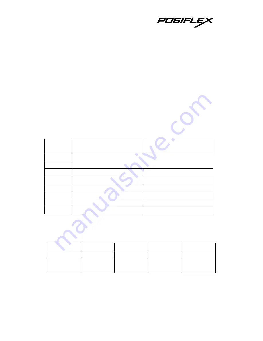
This 8 position DIP switch works as following: 

Switch 

position 

ON OFF 


RS232 baud rate definition or Parallel interface 

definition (ref. separate table below) 

Even parity 

None parity 

XON handshaking 

Hardware handshaking 

Busy on “buffer full” 

Busy on “off line” 

Immediate cut 

Protective cut 

CR code effective 

CR code ineffective 

Factory internal setting 

Application standard mode 

Effect of positions 1 & 2 on baud rate is defined as in table 

below with parity check set according to position 3, number of 
data bits always set to 8, and stop bit set to 1. When the parallel 
interface is used, please set both positions to ON. 

SW Pos. 1 

ON OFF ON OFF 

SW Pos. 2 

ON ON OFF OFF 

Baud rate 
or Interface 

38400 bps / 
(Parallel) 

4800 bps 

9600 bps 

19200 bps 

Switch position 3 defines the parity check regulation in 

serial interface. In Aura, it is selectable between even and none. 


5 - 2 

Содержание Aura PP7000

Страница 1: ...hermal Printer User s Guide Rev A1 IMPORTANT Please read carefully before using this printer Before opening the Top Hood make sure there is no paper jam or cutter jam trouble Read page 3 4 3 5 and Warranty Limit in the user s Manual ...

Страница 2: ...son other than the authorized technicians The user should consult his her dealer for the problem happened Warranty voids if the user does not follow the instructions in application of this merchandise The manufacturer is by no means responsible for any damage or hazard caused by improper application About This Manual This manual is aimed to assist the user to utilize the Aura PP7000 series which i...

Страница 3: ...ING PAPER 2 1 Desk top application 2 1 When to replace paper 2 2 CONNECTING CABLES 2 2 Serial connection 2 2 Parallel connection 2 2 Peripheral connection 2 3 Power connection 2 3 Power on 2 3 Self test 2 4 SPECIAL ADJUSTMENTS 2 5 Paper near end sensor 2 5 Paper roll placement 2 5 Spacer plate 2 6 Paper cutting 2 6 Wall mount application 2 6 MAINTENANCE GUIDES 3 1 MAINTENANCE GUIDE LINES 3 1 GENER...

Страница 4: ...roblems 3 4 Auto cutter problems 3 4 Advanced analysis tool 3 5 SPECIFICATIONS 4 1 PRINTER 4 1 PAPER 4 1 POWER ADAPTOR 4 2 TECHNICAL INFORMATION 5 1 INTERFACES 5 1 Peripheral interface 5 1 SETUP WINDOW 5 2 INTERNAL SWITCH 5 4 SOFTWARE COMMANDS 5 5 Enhancement commands 5 5 CHARACTER CODE PAGES 5 7 ii ...

Страница 5: ...form of a roll at a width of 80 mm standard or 58 mm option The Aura series printer serves the stand alone desk top application as well as the application within a Posiflex integrated POS system equally perfect The Aura series support two types of interface input through different sub codes to the model number The interfaces are RS232 for serial interface and Centronics for parallel interface Aura...

Страница 6: ...to save the packing materials in case the printer needs to be shipped at some point in the future c The printer itself d Thermal paper roll 80 mm wide e One piece of spacer plate f One of the interface cables a Serial cable with 9 pin D sub Female to 9 pin D sub Male connectors for Aura PP7000 PP7000 II S b Parallel cable with 25 pin D sub Male to 25 pin D sub Female connectors for Aura PP7000 PP7...

Страница 7: ...s used to supply power to the printer from the Posiflex POS system h This User s Manual D OPTIONS 58 mm paper guide adaptor can be modified at distributor s site only Kitchen bell Wall mount kit E MAIN PARTS ON THE EXTERIOR Hood Release Top Cover Top Hood Power LED Error LED Paper Out LED FEED Switch Cutter Cover Bottom Cover Power Switch 1 3 ...

Страница 8: ...iew Parallel Connector Power Switch Serial Connector Power Connector Peripheral Connector Frame Ground Bottom View Screws Setup Window Window Plate Screw F INDICATORS Power LED green Error LED red Paper Out LED red 1 4 ...

Страница 9: ...er Use a grounded AC power outlet Use only the power cord and power adaptor furnished with the printer Do not use a power outlet of a circuit shared with any equipment that causes great electrical noise such as motors Do not use a power outlet of a circuit shared with any equipment that uses a lot of power such as a copier or a coffee maker Do not touch any connector contacts to avoid possible ele...

Страница 10: ...yethylene polypropylene or polyester for storage of thermal paper If thermal paper touches anything includes phthalic acid ester plasticizer for a long time the image formation ability may be reduced or the printed image may fade If thermal paper touches diazzo copy paper immediately after copying the printed surface may be discolored Thermal paper must not be stored with the printed surfaces agai...

Страница 11: ...nter to release the hood 2 Raise the released hood wide open manually 3 Drop the thermal paper roll inside the printer in the orientation as shown in the picture 4 Close the hood back leaving the tail of the paper roll coming out of the opening between the hood and the top cover Tear off excessive paper 2 1 ...

Страница 12: ...ale connector of RS232 cable to this port for serial application Please note that when serial connection is used there must be no cable connection at the parallel port on the printer The default protocol used in serial connection is 19200 bps none parity 8 data bits 1 stop bit Set in setup window the switch positions both 1 and 2 to OFF leaving the rest unchanged as factory default setting 2 Paral...

Страница 13: ...stead 4 Power connection The power connector is a 3 pin jack between the peripheral connector and the parallel connector Either a Posiflex supplied power adaptor or a printer power cable from a Posiflex POS system can be connected to this connector to supply power for this printer During insertion of the power plug be sure to hear the click to obtain a firm contact CAUTION Before doing the inserti...

Страница 14: ... while turning the on off switch on The printer will then perform a self test A sample slip of self test result is printed below Please note that both serial and parallel interfaces are indicated That means the printer is working on an autosensing and autoselect algorithm The header is printed in text mode and the rest part of this slip is printed in page mode If FEED button is pressed at this 2 4...

Страница 15: ...n outer diameter is between 18 and 22mm This adjustment allows sensor activation on paper roll overall diameter between 21 and 23 6 mm unless for too light bobbins Remember for smaller roll diameter the sensor head should go higher Sensor Head Fixing Screw 2 Paper roll placement When the paper roll to put back in is already nearly used up the paper roll must be placed in the way that the paper rol...

Страница 16: ...nsates 1 mm paper roll width shortage There will be 1 spacer plate in the accessory of the printer If the user uses narrower paper roll and requires more spacer plates it can be purchased from Posiflex 4 Paper cutting The paper advance after a protective cut is now set to 12 mm In case the user uses direct cut instead of protective cut to have something like a logo printed on top of each slip it i...

Страница 17: ...se soft hair brush or compressed air to clear away any dust or paper scraps accumulation inside the printer Check also the area of the auto cutter regularly C PRINT HEAD CLEANING The print head is located underneath the roll paper passage at the exit as in the picture below You can clean the thermal elements of the print head and paper sensor gently using a cotton swab moistened with isopropyl alc...

Страница 18: ...aper roll is not installed or is at or near the end Install a new paper roll If the Paper Out LED is OFF please check if the print hood is properly closed There are 2 internal check points inside the printer to assure the locking of the hood for a decent printing Therefore any dislocation of the hood may cause an error status and inhibition to printing Press down the hood at middle of the opening ...

Страница 19: ...f test fails contact your dealer or a qualified service person Poor printing quality Contaminants like paper scraps and dusts on the thermal print head can lower the print quality drastically Clean the print head as described in previous section Printer trembles when printing Since PP7000 II prints at 180 mm sec that is extremely high speed the printer may tremble due to frequent engagement of the...

Страница 20: ...any contaminants accumulated in the cutter track above the thermal elements Auto Cutter Track Thermal Elements 4 Auto Cutter Problems In case any foreign materials like a staple or paper clip or excessive paper scraps fall into the auto cutter mechanism the auto cutter may lock up and so does the print hood In such case please pull the cutter cover forward to expose the cutter mechanism Apply some...

Страница 21: ... foil Open Cutter Cover when hood locked 5 Advanced Analysis Tool This printer supports Hexadecimal Dump for experienced user to view exactly what data is received by the printer This can be useful in finding software problems To start the dump mode Turn off printer Open print hood Hold down FEED button while turning printer on Close the hood To stop the dump mode Press the FEED button to print ou...

Страница 22: ......

Страница 23: ...aper feed method Friction auto feed Paper load method Drop and use Auto cutter capability Partial cut 1 point at center left Manual cutter Saw tooth blade Dot Pitch 0 125 x 0 125 mm Input power type DC Input voltage 24 V 5 Dimension mm 148 W x 199 D x 144 H Weight 1 35 Kg net B PAPER Paper type Thermal roll paper Paper roll formation External side is heat sensitive side Paper width 80 or 58 0 1 mm...

Страница 24: ...MENT INPUT VOLTAGE 100 V AC 250 V AC INPUT FREQUENCY 50 60 HZ INPUT CURRENT 1 5 A MAX 115 V AC OUTPUT VOLTAGE 24 V DC OUTPUT POWER 60 W STATIC LOAD 0 A 2 5 A OUTPUT REGULATION 5 MTBF 30 000 HRS EMI STANDARDS VDE B FCC B VCCI B 4 2 ...

Страница 25: ...ng an optional split cable 20867023800 CCBLA 238 Aura series controls two cash drawers through this connector Please connect the CR1 plug to the cash drawer CRA to be opened by command Esc p 1 n1 n2 and the CR2 plug to the cash drawer CRB to be opened by command Esc p 0 n1 n2 6P6C RJ11 jack 6 1 6 1 6 pin plug PIN Definition Description 1 FG Frame ground 2 CRB Drawer kick for cash drawer controlled...

Страница 26: ...llowing Switch position ON OFF 1 2 RS232 baud rate definition or Parallel interface definition ref separate table below 3 Even parity None parity 4 XON handshaking Hardware handshaking 5 Busy on buffer full Busy on off line 6 Immediate cut Protective cut 7 CR code effective CR code ineffective 8 Factory internal setting Application standard mode Effect of positions 1 2 on baud rate is defined as i...

Страница 27: ...ignal to the host Consequently the printing may be stopped even when there is still a long way to go before the paper roll is actually exhausted For switch position 6 when it is set to OFF there will be a 20 mm paper feed before cutting when software does not define this point and there will be further 10 mm paper after cutting to prevent paper jam Before setting this switch to ON please make sure...

Страница 28: ...line 4 Reserved N A N A For switch position 1 when it is set to ON the printer runs in high speed mode This is the default setting as the printer is delivered However depending on the print content f i the printer is used for printing bar codes that have to be dark enough it could be wiser to set the printer to work in power saving mode by changing the switch to OFF The printer could run smoother ...

Страница 29: ...ng commands are included in the printer firmware version since ver 3 2 ESC o Beep command GS o m Beep definition 0 m 16 default 3 seconds ESC p m n1 n2 Cash drawer kick or kitchen bell drive command GS p m n Beep when cash drawer remain open 0 m 256 n 0 or 1 Explanations as below ESC o Beep command Hexadecimal codes are 1B 6F Printer beeps when this command is received per condition set by beep de...

Страница 30: ... this command is sent to the printer multiple times consecutively the bell will ring for about half a second and rest for also about half a second then ring again for multiple times GS p m n Beep when cash drawer remain open 0 m 256 n 0 or 1 Hexadecimal codes are 1D 70 m n If the cash drawer connected to the printer remains open for more than m seconds the printer beeps until the drawer is closed ...

Страница 31: ...many UK Denmark I Sweden Italy Spain Japan Norway Denmark II Spain II Latin America Korea for character set code from 0 to D and Ex Jugoslavia for character set code F If any undefined code 00 to 1F or an undefined ESC FS or GS command sequence beyond these tables is received the code or the sequence of codes will be discarded However when image print data character registration data or command pa...

Страница 32: ......

Страница 33: ......

Страница 34: ......

Страница 35: ......

Страница 36: ......

Страница 37: ......

Страница 38: ......

Страница 39: ......

Страница 40: ......

Страница 41: ......

Страница 42: ......

Страница 43: ......

Страница 44: ......

Отзывы: