100
(3) Jumpers
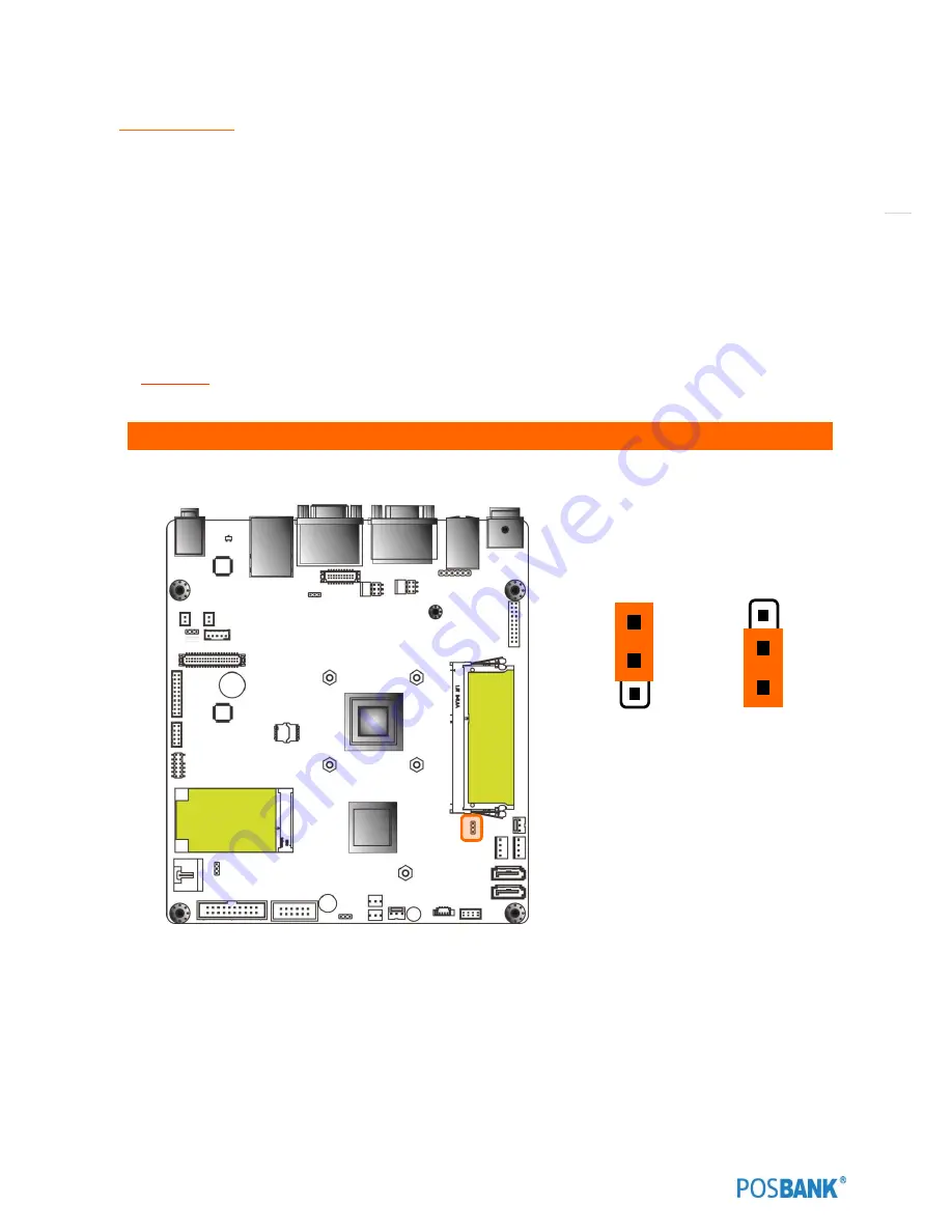
Clear CMOS (CMOS1)
This jumper allows you to clear the Real Time Clock (RTC) RAM in CMOS. You can clear the CMOS memory of date,
time, and system setup parameters by erasing the CMOS RTC RAM data. The onboard button cell battery powers the
RAM data in CMOS, which includes system setup information such as system passwords.
To erase the RTC RAM:
1.
Turn OFF the computer and unplug the power cord.
2.
Remove the onboard battery.
3.
Move the jumper cap from pins 1-2 (default) to pins 2-3. Keep the cap on pins 2-3 for about 5~10 second,
them move the cap back to pins 1-2.
4.
Re-install the battery.
5.
Plug the power cord and turn ON the computer.
6.
Hold down the <Del> key during the boot process and enter BIOS setup to re-enter data
CAUTION:
Except when clearing the RTC RAM, never remove the cap on CLRTC jumper default position. Removing
the cap will cause system boot failure!
1. Clear CMOS (CMOS1)
1
Clear CMOS
Normal (Default)
1
Содержание ANYSHOP PRIME
Страница 1: ...Point of sale system ANYSHOP PRIME USER manual ANYSHOP_PRIME PBUM_E Rev001 150421...
Страница 3: ...3...
Страница 6: ...6 1 Specification Outside size...
Страница 7: ...7 2 Specification Module Explode view...
Страница 8: ...8 3 Specification Body ExplodeView...
Страница 9: ...9 4 Specification Monitor ExplodeView...
Страница 10: ...10 5 Specification Hinge Explode view...
Страница 23: ...23 Side view 1 I O port cover 2 USB port option 3 Customer display Option 4 Storage Default HDD 2 1 4 2 3...
Страница 25: ...25 Standard I O port J1900...
Страница 30: ...30 10 Setting up Printer Connection Connect printer cable to either Serial USB port as required...
Страница 46: ...46 Mother Board Step7 Remove the 8 Hexagon bolts and remove the 4 screws Step8 Replace the motherboard...
Страница 57: ...57 CDP Option Position Put holes in the sample place Image reference VGA1 connect Mother board VGA1 connect...
Страница 58: ...58 CDP Option Step11 Reassemble back cover procedure of Step1 4...
Страница 64: ...64 2nd display 9 7inch 12 1 inch monitor Option Position Put holes in the sample place Image reference VGA Port...
Страница 67: ...67 Step17 Change VGA 12V Configuration Disabled to Enabled Step18 Press the F4 key to save and exit...
Страница 69: ...69 MSR OPTION Step3 Assemble 2 screws from side using hand as shown above Step 4 Assemble the MSR...
Страница 70: ...70 MSR Option Step 5 Monitor under put holes in the sample place...
Страница 76: ...76 USB Option Step7 Remove the USB module Step8 Replace the USB module...
Страница 85: ...85 Memory Option Memory installation position...
Страница 86: ...86 Memory Option Step8 Assemble the RAM SODIMM from the socket Retaining clip DDR SODIMM notch...
Страница 87: ...87 Memory Option Step9 Reassemble back cover procedure of Step1 4...
Страница 91: ...91 Cash drawer Option Step7 Assemble a hexagon bolt and fasten Screw to cash drawer Same image about step6...
Страница 94: ...94 Cash drawer Option Step10 Reassemble back cover procedure of Step1 4...
Страница 102: ...102 4 LVDS Backlight power selection JLVDS_P3 5 VGA2 power selection CRT_SEL 1 3 3V 5V Default 1 1 5V 12V Default 1...
Страница 103: ...103 6 OnboardTouch function Enable Disable selection USB_SEL 1 Disable Enable Default 1...


