background image


15 


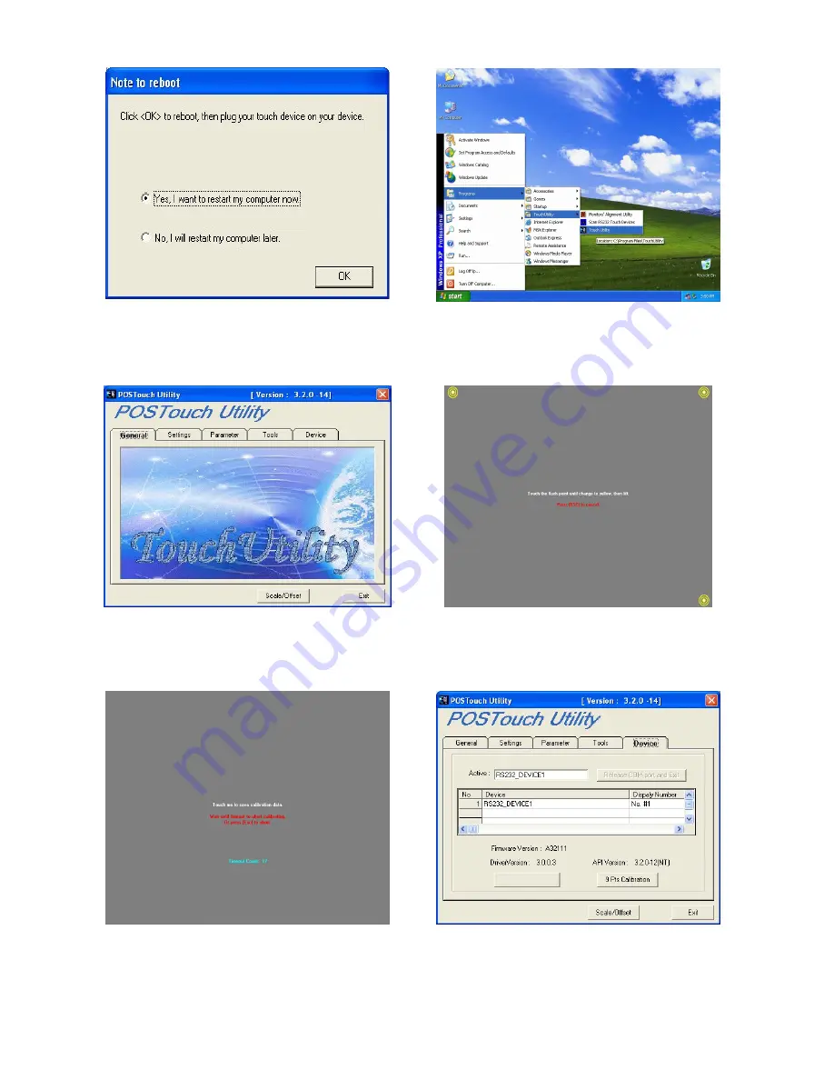
k. Select “Yes, I want to restart my computer 

now.”, then click “OK” button. 


l.  After  the  computer  has  restarted,  select 

the “Touch Utility” on the desktop. 


m.  Click  “Scale/Offset”  button  on  the  POS 

Touch Utility window. 


n.  Touch  the  flash  point  until  it  changes  to 

yellow for alignment. 


o. Touch any spot on the screen for saving 

calibration data. 


p. Select “Device” on the POS Touch Utility 

window, then click “9 Pls Calibration” 

button on the POS Touch Utility window. 


Содержание POS122

Страница 1: ...1 Touch POS Monitor POS 120 Series InstallationGuide 2006 December V1 4...

Страница 2: ...iator or heat register or in a built in installation unless proper ventilation is provided 7 This product should be operated from the type of power indicated on the marking label If you are not sure o...

Страница 3: ...d be taken to the waste collection centres for activation of the treatment collection recycling and disposal procedure To prevent possible harm to the environment or human health from uncontrolled was...

Страница 4: ...estored while the system is switched on hot plug POS monitor DC power is removed and restored while the system is switched on hot plug If the touch panel stops responding due to one of the above condi...

Страница 5: ...2 REAR VIEW 7 2 3 OSD CONTROL PANEL 8 3 ON SCREEN DISPLAY 9 4 SPECIFICATION 10 5 DRIVER INSTALLATION 11 5 1 ELO TOUCH DRIVER INSTALLATION 11 5 2 POS TOUCH DRIVER INSTALLATION 11 6 JUMPER SETTINGS 17...

Страница 6: ...6 1 Accessories a Optional Audio Cable b Driver CD c COM Port Cable option for MSR d Power Cord e USB Cable for USB Touch f VGA Cable...

Страница 7: ...current that can be drawn from each COM port is 500 mA Function Assignment 1 VGA VGA Input 2 COM1 Magnetic Card Reader 3 COM2 Touch Screen 4 USB USB Type B 5 PWR1 DC 19V IN 6 KB IN Magnetic Card Reade...

Страница 8: ...Assignment 1 Power Button LCD Monitor on off 2 Menu Button To get into video setup mode 3 Left Button 4 Right Button Left and Right buttons for video function adjustment purpose 5 Select Button Moves...

Страница 9: ...Traditional Chinese Language Simplied Chinese Note 1 Press the Menu button to make adjustments then press the Menu button to exit the menu if you press the Menu button to exit the OSD window the syste...

Страница 10: ...for touch OSD Button Power Menu Video Function Adjustment Exit Rear I O PS 2 2 for MSR Keyboard Serial COM 2 For MSR reserved for touch Line Input 1 port Optional Internal Speaker 2 x 2W Optional Powe...

Страница 11: ...ty CD datasheet POS120Series POS120 Series installation guide The following procedures s for Windows XP other platforms are similar 5 1 ELO Touch Driver Installation a Click sw500930 on the My Compute...

Страница 12: ...the on the Select the COM ports window g Select COM5 and click the Next button on the Choose the COM ports window h Click the Next button on the You have selected the COM ports window i Click the Fini...

Страница 13: ...instructions on the screen to do a three point calibration of the touch panel 5 2 POS Touch Driver Installation a Click Setup on My Computer window b Click Next button on the Welcome window c Click Y...

Страница 14: ...ndow f Click Next on the Select Components Folder window g Click Next on the Start Copying files window h Driver is installing now i Click Finish on the InstallShield Wizard Complete window j Click Co...

Страница 15: ...Utility on the desktop m Click Scale Offset button on the POS Touch Utility window n Touch the flash point until it changes to yellow for alignment o Touch any spot on the screen for saving calibratio...

Страница 16: ...h point on the screen until it changes to yellow for linearizing alignment r Touch any spot on the screen for saving linearizing data s Click Exit button on the POS Touch Utility window then the drive...

Страница 17: ...1 M B Jumper Setting 1 VGA Power Enable Selection Function JP3 1 2 Power Enable SHORT Power Disable OPEN 2 MSR Power Selection Function JP7 1 2 JP7 3 4 PS2 MSR SHORT default N C SERIAL MSR N C SHORT N...

Страница 18: ...7 1 Base Cover Cable Holder Cables route through the holder gap for cable management Assignment 1 USB Cable Type B 2 PS2 Cable 3 PS2 Cable 4 COM Port Cable 5 COM Port Cable 6 VGA Cable Cable Holder 1...

Отзывы: