background image

BIOS Setup Information


WADE-8011/WADE-8012 User’s Manual 

4-7 


Wake system with Fixed Time 

Enabled or Disabled system wake on alarm event. When Enabled, system will wake 
on the hr::min::sec specified. 
Choices: Disabled, Enabled 
 

Wake up hour 

Select 0-23 for example enter 3 for 3am and 15 for 3pm. 
Choices: 0-23 
 

Wake up minute 

Choices: 0-59 
 

Wake up second 

Choices: 0-59 
 

Wake system with Dynamic Time 

Use this item to enable or disable system wake on alarm event. When set as [Enabled], 
system will wake on the current plus increased minute(s). 
Choices: Disabled, Enabled 
 

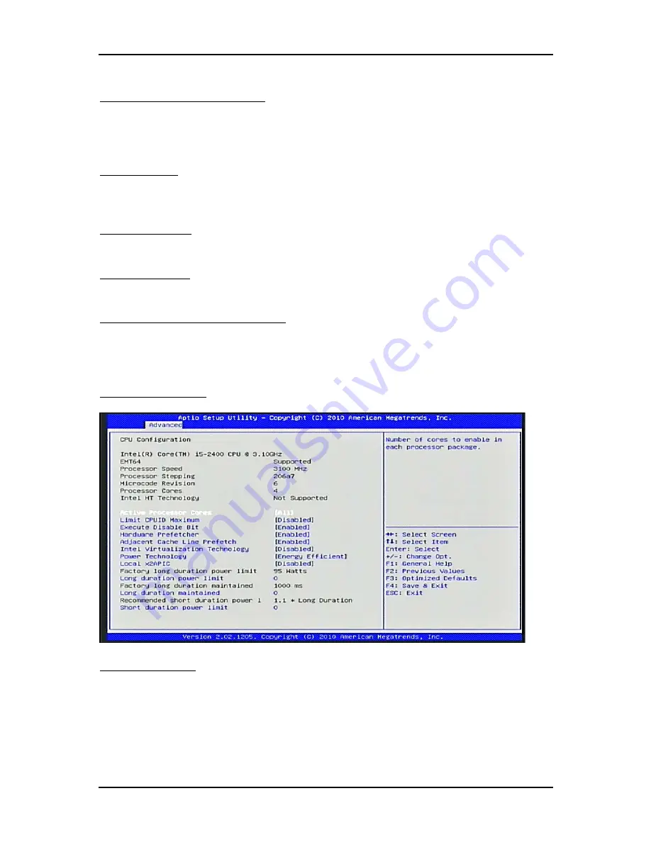
CPU Configuration


These items show the advanced specifications of your CPU. Read only. 


Hyper-Threading 

Enabled for Windows XP and Linux (OS optimized for Hyper-Threading 
Technology) and Disabled for other OS (OS not optimized for Hyper-Threading 
Technology). When Disabled only one thread per enabled core is enabled. 
Choices: Disabled, Enabled. 

Содержание WADE-8011

Страница 1: ...WADE 8011 WADE 8012 Mini ITX Board User s Manual Version 1 4 Copyright Portwell Inc 2013 All rights reserved All other brand names are registered trademarks of their respective owners...

Страница 2: ...3 2 Main Memory 3 4 3 3 Installing the Single Board Computer 3 5 3 3 1 Chipset Component Driver 3 5 3 3 2 Intel Integrated Graphics Controller 3 5 3 3 3 On board Gigabit Ethernet Controller 3 5 3 3 4...

Страница 3: ...ry and Compact Flash to get a safe installation and provides a programming guide of Watch Dog Timer function Chapter 4 BIOS Setup Information Specifies the meaning of each setup parameters how to get...

Страница 4: ...to push innovation with an architecture designed to deliver quality performance and industry leading I O technologies on platforms powered by the Intel Dual Core Quad Core processor WADE 8011 WADE 80...

Страница 5: ...t and maintenance 1 3 Product Specification z Main Processor Intel Dual Core Quad Core LGA1155 processor CPU clock bus 1333 1066 800 MHz z Chipset Intel C206 Express chipset WADE 8011 Intel Q67 Expres...

Страница 6: ...6 69 z Power Requirements Configuration CPU Type Intel Core i5 2400 CPU 3 10GHz ES L3 6M SBC BIOS Portwell Inc WADE 8011 WADE 8012 BIOS Rev R1 00 E1 Memory Apacer PC3 8500 2GB 1 ELPIDA J1108BFBG DJ E...

Страница 7: ...1 3 1 Mechanical Drawing 0 4 53 12 50 11 2 9 0 1 6 0 7 6 0 14 4 2 2 8 5 0 0 98 32 21 85 41 35 61 87 88 19 117 5 1 16 1 1 6 166 64 162 73 162 64 165 44 74 45 15 3 7 7 122 02 143 55 126 73 17 94 7 92 0...

Страница 8: ...System Overview WADE 8011 WADE 8012 User s Manual 1 5 0 170 0 0 170 6 35 1 63 83 4 90 159 84 136 98 Keep out zone 6 4 Hole 8 Pad_Each side...

Страница 9: ...em Overview WADE 8011 WADE 8012 User s Manual 1 6 1 4 System Architecture All of details operating relations are shown in WADE 8011 WADE 8012 System Block Diagram WADE 8011 WADE 8012 System Block Diag...

Страница 10: ...tings shipped from factory are marked with an asterisk 2 1 Jumper Setting In general jumpers on the single board computer are used to select options for certain features Some of the jumpers are design...

Страница 11: ...Hardware Configuration WADE 8011 WADE 8012 User s Manual 2 2 Figure 2 1 WADE 8011 WAD 8012 Jumper and Connector Locations...

Страница 12: ...e schematically depicted in this manual as follows JP1 CMOS Clear JP1 Function 1 2 Short Normal Operation 2 3 Short Clear CMOS Contents JP5 WDT Selection JP5 Function Short Enable Open Disable JP6 ATX...

Страница 13: ...Express 1 2 Open 3 4 Short Reserved 1 2 Open 3 4 Open 1x16 PCI Express PCIe bifurcation support varies with the Processor and PCH SKUs used JP8 COM2 J2B Interface Selection JP8 Function 5 6 9 11 10 12...

Страница 14: ...ne_in Line_out J5 RJ45 USB Connector J6 RJ45 USB Connector J7 PCIe x 1 USB Connector J9 TPM Connector Reserved J10 12V Power Connector Connect to CPU J11 WDT LED Connector J12 J15 External USB Connect...

Страница 15: ...ription Pin No Signal Description 1 3V 2 3VSBY 3 3V 4 3VSBY 5 3V 6 5V 7 3V 8 5V 9 3V 10 5V 11 3V 12 5V 13 3V 14 1 5V 15 Ground 16 1 5V 17 n c 18 1 5V 19 n c 20 Ground 21 Ground 22 n c 23 n c 24 n c 25...

Страница 16: ...3 Ground 64 USB_Data 65 PCIE_TX 66 USB_Data 67 PCIE_TX 68 SMB_DATA 69 PLT_RST 70 SMB_CLK J9 TPM Pin Header Pin No Signal Description Pin No Signal Description 1 PCKL_TPM 2 GND 3 LFRAME 4 X 5 SIO2_PLTR...

Страница 17: ...2 LED J12 J15 External USB Connector Pin No Signal Description Pin No Signal Description 1 5V Dual 2 5V Dual 3 USB 4 USB 5 USB 6 USB 7 Ground 8 Ground 9 Key no pin 10 N C Note 5V Dual is always availa...

Страница 18: ...10 GPIO12 11 GPIO5 12 GPIO13 13 GPIO6 14 GPIO14 15 GPIO7 16 GPIO15 17 Ground 18 5V Note All General Purpose I O ports can only apply to standard TTL 5 signal level 0V 5V and each Fan Front Panel Pin H...

Страница 19: ...E 8012 User s Manual 2 10 J18 J19 J20 J21 SATA GEN2 Connector Pin No Signal Description 1 Ground 2 TX 3 TX 4 Ground 5 RX 6 RX 7 Ground J22 J23 SATA GEN3 Connector Pin No Signal Description 1 Ground 2...

Страница 20: ...WADE 8012 User s Manual 2 11 J26 System Fan Connector Pin No Signal Description 1 Ground 2 Fan speed control 3 Fan on off output J27 CPU Fan Connector Pin No Signal Description 1 Ground 2 12V 3 Fan o...

Страница 21: ...sed to help you set up onboard PCI device and handle Watch Dog Timer WDT and operation of GPIO in software programming 3 1 Intel LGA 1155 Processor LGA 1155 CPU Socket LGA 1155 CPU Please remember to...

Страница 22: ...155 CPU Installation Steps Before install the CPU please make sure to turn off the power first 1 Open the load lever 2 Lft the load lever up to fully open 3 Rmove the plastic cap on the CPU socket Bef...

Страница 23: ...put down the CPU in the socket housing frame Note that alignment keys are matched 5 Make sure the CPU has been seated well into the socket If not take out the CPU and reinstall 6 After confirming the...

Страница 24: ...lated settings can be detected by BIOS via SPD interface For system compatibility and stability do not use memory module without brand Memory configuration can be set to either one double sided DIMM i...

Страница 25: ...recognize To overcome this compatibility issue for Windows Operating Systems such as Windows XP please install its INF before any of other Drivers are installed You can find very easily this chipset...

Страница 26: ...mmable time out counter and a control and status register WDT Controller Register There are two PNP I O port addresses that can be used to configure WDT 2Eh EFIR Extended Function Index Register for i...

Страница 27: ...r to disable WDT immediately To ensure a successful accessing to the content of desired Control Register the sequence of following program codes should be step by step run again when each register is...

Страница 28: ...er 0x73 0x05 printf System will reset in 5 seconds n return 0 3 6 GPIO The motherboard provides 8 input output ports that can be individually configured to perform a simple basic I O function GPIO Pin...

Страница 29: ...8 GPIO11 9 GPIO4 10 GPIO12 11 GPIO5 12 GPIO13 13 GPIO6 14 GPIO14 15 GPIO7 16 GPIO15 17 Ground 18 5V Note All General Purpose I O ports can only apply to standard TTL 5 signal level 0V 5V and each Fan...

Страница 30: ...ite offset x x n offset value Or register void Or_Register unsigned char offset unsigned char value outp SIO_Port offset outp SIO_Port 1 inp SIO_Port 1 value printf Write offset x x n offset value And...

Страница 31: ...er 0xC8 0x06 11 12 Or_Register 0xCB 0x80 47 Or_Register 0xCC 0x01 50 Or_Register 0xCE 0xF0 74 75 76 77 Set Input And_Register 0xC8 0xEF 14 And_Register 0xCA 0x1F 35 36 37 And_Register 0xCE 0xF0 70 71...

Страница 32: ...ult 0 printf Test fail n return 1 Set Input And_Register 0xC8 0xF9 11 12 And_Register 0xCB 0x7F 47 And_Register 0xCC 0xFE 50 And_Register 0xCE 0x0F 74 75 76 77 Set output Or_Register 0xC8 0x10 14 Or_R...

Страница 33: ...inp GPIO_Base 2 0x1F 35 36 37 outp GPIO_Base 6 inp GPIO_Base 6 0xF0 70 71 72 73 result 1 if inp GPIO_Base 0 0x06 0x00 result 0 11 12 if inp GPIO_Base 3 0x80 0x00 result 0 47 if inp GPIO_Base 4 0x01 0x...

Страница 34: ...ram will prompt the user to enter the SETUP program Some errors are significant enough to abort the start up 4 1 Entering Setup Launch System Setup Power on the computer and the system will start POST...

Страница 35: ...Information Memory Information These items show the firmware and memory specifications of your system Read only System Language Choose the system default language Choices English System Date The date...

Страница 36: ...tems of special enhanced features Launch PXE OpROM Enabled or Disabled Boot Option for Legacy Network Devices Choices Disabled Enabled Launch Storage OpROM Enabled or Disabled Boot Option for Legacy M...

Страница 37: ...ERR Generation Enables or Disables PCI Device to Generate SERR Choices Disabled Enabled Relaxed Ordering Choices Disabled Enabled Extended Tag If Enabled allows Device to use 8 bit Tag field as a requ...

Страница 38: ...abled ACPI Auto Configuration Choices Enabled Disabled Enabled Hibernation Enables or Disables System ability to Hibernate OS S4 Sleep State This option may be not effective with some OS Choices Enabl...

Страница 39: ...TPM Reset of platform is required TPM State Turn TPM Enable or Disable NOTE Your Computer will reboot during restart in order to change State of TPM Pending TPM operation Schedule TPM operation NOTE...

Страница 40: ...Choices 0 59 Wake system with Dynamic Time Use this item to enable or disable system wake on alarm event When set as Enabled system will wake on the current plus increased minute s Choices Disabled E...

Страница 41: ...streamer prefetcher Choices Disabled Enabled Adjacent Cache Line Prefetch To turn on off the prefetching of adjacent cache lines Choices Disabled Enabled Intel Virtualization Technology When enabled...

Страница 42: ...Long duration maintained Time window which the long duration power is maintained Choices 0 32000 Short duration power limit Short duration power limit in Watts Choices 0 255 SATA Configuration SATA D...

Страница 43: ...ME SMBus Thermal Reporting Configuration Choices Disabled Enabled Thermal Data Reporting Choices Disabled Enabled SMBus Buffer Length SMBus Block Read message length for EC Choices 1 2 5 9 10 14 20 T...

Страница 44: ...nabled Thermal Sensor on DIMM3 Choices Disabled Enabled Alert Enable Lock Lock all Alert Enable settings Choices Disabled Enabled PCH Alert Choices Disabled Enabled DIMM Alert Choices Disabled Enabled...

Страница 45: ...oices 128MB 256MB Maximum IGD Boot Type Select the Video Device which will be activated during POST This has no effect if external graphics present Choices VBIOS Default CRT EFP EFP2 EFP3 CRT EFP Spre...

Страница 46: ...is is a workaround for OSes without EHCI hand off support The EHCI ownership change should claim by EHCI driver Choices Disabled Enabled Port 60 64 Emulation Enables I O port 60h 64h emulation support...

Страница 47: ...it properly reports itself to the Host Controller AUTO uses default value for a Root port it is 100ms for a Hub port the delay is taken from Hub descriptor Choices Auto Manual Info Report Configurati...

Страница 48: ...Serial Port Choices Disabled Enabled Change Settings Select an optimal setting for Super IO Device Choices Auto IO 3F8h IRQ 4 O 3F8h IRQ 3 4 5 6 7 10 11 12 IO 2F8h IRQ 3 4 5 6 7 10 11 12 IO 3E8h IRQ 3...

Страница 49: ...led 10 Seconds 20 Seconds 30 Seconds 40 Seconds 50 Seconds 60 Seconds Case Open Warning If this function is set to Enabled and the case had been previously opened the system will automatically display...

Страница 50: ...hoices 60 65 70 75 Smart Fan2 Control Smart Fan2 Function Choices Disabled Enabled Smart Fan2 Start Smart Fan2 Start Temperature Choices 25 30 35 40 45 50 55 60 65 70 Fan2 Full Speed Fan2 Full Speed T...

Страница 51: ...ble WatchDog Timer Serial Port Console Redirection Console Redirection Console Redirection Enable or Disable Terminal Type VT UTF8 is the preferred terminal type for out of road management The next be...

Страница 52: ...011 WADE 8012 User s Manual 4 19 4 4 Chipset This menu controls the advanced features of the onboard North Bridge South Bridge and ME Subsystem North Bridge Low MMIO Align Low MMIO resources align at...

Страница 53: ...nal Graphics Device Choices Disabled Enabled IGD Multi Monitor Enable Disable IGD Multi Monitor by Internal Graphics Device Choices Disabled Enabled PCI Express Port Choices Disabled Enabled Auto PEG...

Страница 54: ...hoices Disabled Enabled Restore AC Power Loss Specify what state to go to when power is re applied after a power failure G3 State Choices Power Off Power On Last State SLP_S4 Assertion Stretch Enable...

Страница 55: ...tery Enabled in S4 and S5 Azalia HD Audio Enabled Disabled Azalia HD Audio Choices Disabled Enabled Azalia Intermal HDMI codec Enabled Disabled internal HDMI codec for Azalia Choices Disabled Enabled...

Страница 56: ...ess Port 7 Choices Disabled Enabled Auto PCI Express Port 8 Choices Disabled Enabled Auto PCIe Sub Decode Enabled Disabled PCIe Sub Decode Port This option is available when Subtractive Decode Agent E...

Страница 57: ...Disabled Enabled USB Port 0 13 Enabled Disabled USB Port 0 13 Choices Disabled Enabled ME Subsystem ME Subsystem Use this item to enable or disable ME subsystem ME Temporary Disable Use this item to e...

Страница 58: ...ables or disables Quiet Boot option This BIOS feature determines if the BIOS should hide the normal POST messages with the motherboard or system manufacturer s full screen logo When it is enabled the...

Страница 59: ...e display mode of optional ROM Choices Force BIOS Keep Current Interrupt 19 Capture Enabled Allows Option ROMs to trap Int 19 Interrupt 19 is the software interrupt that handles the boot disk function...

Страница 60: ...tup Information WADE 8011 WADE 8012 User s Manual 4 27 4 6 Security Use this menu to set supervisor and user passwords Administrator Password Set Setup Administrator Password User Password Set User Pa...

Страница 61: ...ion Save configuration and reset Discard Changes and Reset Reset system setup without saving any changes Restore Defaults Restore Load Default values for all the setup options Built in EFI Shell Boot...

Страница 62: ...are only two connectors that must be connected J10 4 pins CPU 12V main power connector J13 24 pins ATX Power Connector Figure Serial ATA Hard Disk Setting for IDE AHCI Unlike IDE bus each Serial ATA c...

Страница 63: ...nter system failures that result in malfunction of any device To make sure that you have a successful start with WADE 8011 WADE 8012 it is recommended when going with the boot up sequence to hit DEL k...

Страница 64: ...very common that users would like to disable a certain device port to release IRQ resource A few good examples are Disable Serial Port1 to release IRQ 4 Disable Serial Port2 to release IRQ 3 Etc A qu...

Страница 65: ...egister an account http www portwell com tw support newmember php 2 Input your User name and password to log in the download center 3 Select the Search download to input the keyword WADE 8011 8012 4 F...

Страница 66: ...A Graphics B000 B7FF 32K Unused B800 BFFF 32K VGA Text C000 CD7F 54K Video ROM CD80 EFFF 138K Unused F000 FFF 64K System ROM HMA 64K First 64k Extended Interrupt Request Lines IRQ Peripheral devices c...

Страница 67: ...Troubleshooting WADE 8011 WADE 8012 User s Manual 5 6 IRQ 13 System ROM Coprocessor Error IRQ 14 System ROM Hard Disk Event IRQ 15 Unassigned Usable IRQ...

Отзывы: