


Fig. 11
5.6.9
The control is now ready for use with the burner.
5.6.10
If the handset is misplaced you can “page it” by pressing the (+) button
only on the control valve on the fire for a period of 5 seconds. The
handset will flash and make an audible noise to help you locate it.
Once you find the handset with one hand ensure your hand
is wrapped around the back and that your hand is in contact with both
sides of the handset then the audible noise will cease. The flashing
and sound will last for 60 seconds each time the handset is paged as
described. If not found in 60 seconds page the handset again until
located.
50
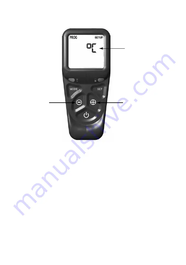
Celsius or Fahrenheit
temperature display, press
the + or - buttons as shown
to toggle between these two
settings and set the correct
time of day.
+ button
- button