background image

6

ELECTRICAL REQUIREMENTS AND SAFETY

POWER SUPPLY AND MOTOR SPECIFICATIONS

To avoid electrical hazards, fire hazards, 

or damage to the tool, use proper circuit 

protection. Use a seperate electrical circuit for 

your tool. Your saw is wired at the factory for 

120 V operation. Connect to a 120 V, 10 Amp 

circuit and use a 10 Amp time delay fuse or 

circuit breaker. To avoid shock or fire, if power 

cord is worn, cut, or damaged in any way, have it 

replaced immediately.
GROUNDING INSTRUCTIONS

This tool must be grounded while in use to 

protect the operator from electrical shock.
IN THE EVENT OF A MALFUNCTION OR 

BREAKDOWN,

 grounding provides a path of least 

resistance for electric currents and reduces the 

risk of electric shock. This tool is equipped with an 

electrical cord that has an equipment-grounding 

conductor and a grounding plug. The plug must be 

plugged into a matching receptacle that is properly 

installed and grounded in accordance with all local 

codes and ordinances.

DO NOT MODIFY THE PLUG PROVIDED. 

If it will 

not fit the receptacle, have the proper receptacle 

installed by a qualified electrician.

IMPROPER CONNECTION

 of the equipment 

grounding conductor can result in risk of electric 

shock. The conductor with the green insulation 

(with or without yellow stripes) is the equipment 

grounding conductor. If repair or replacement of 

the electrical cord or plug is necessary, do not 

connect the equipment grounding conductor to a 

live terminal.

CHECK

 with a qualified electrician or service person 

if you do not completely understand the grounding 

instructions, or if you are not certain the tool is 

properly grounded.

USE only 3-wire extension cords that have 

three-pronged grounding plugs with three-pole 

receptacles that accept the tool’s plug. Repair or 

replace damaged or worn cords immediately.

Use a separate electrical circuit for your tool. This 

circuit must not be less than #16 wire and should 

be protected with a 10 Amp time lag fuse. Before 

connecting the motor to the power line, make sure 

the switch is in the off position and the electric 

current is rated the same as the current stamped on 

the motor nameplate. Running at a lower voltage will 

damage the motor.

GUIDELINES FOR EXTENSION CORDS
USE THE PROPER EXTENSION CORD.

 Make 

sure your extension cord is in good condition. Use 

an extension cord heavy enough to carry the 

     WARNING

!

     WARNING

!

current your product will draw. An undersized cord 

will cause a drop in line voltage resulting in loss of 

power, overheating and burning out of the motor. 

The table below shows the correct size to use 

depending on cord length and nameplate ampere 

rating. If in doubt, use the next heavier gauge. The 

smaller the gauge number, the heavier the cord. 

Make sure your extension cord is properly wired 

and in good condition. Always replace a damaged 

extension cord or have it repaired by a qualified 

technician before  using it. Protect your extension 

cords from sharp objects, excessive heat and damp 

or wet areas. 

This tool is for indoor use only. Do not expose to 

rain or use in damp locations. 

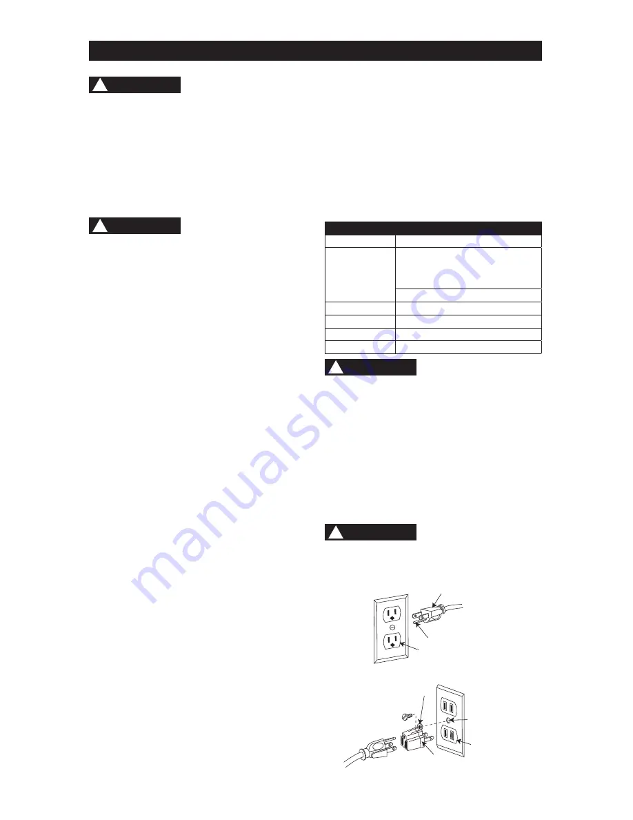
This tool is intended for use on a circuit that has 

a receptacle like the one illustrated in Fig. 1. 

Fig. 1 shows a three-pronged electrical plug and 

receptacle that has a grounding conductor. If a 

properly grounded receptacle is not available, an 

adapter (Fig. 2) can be used to temporarily connect 

this plug to a two-contact grounded receptacle. The 

adapter (Fig. 2) has a rigid lug extending from it that 

MUST be connected to a permanent earth ground, 

such as a properly grounded receptacle box.

In all cases, make certain the receptacle is 

properly grounded. If you are not sure, have a 

qualified electrician check the receptacle.

MINIMUM GAUGE FOR EXTENSION CORDS (AWG)

Ampere Rating 

Total Length of Cord

More

Than

Not More 

Than

120 V   25          50         100        150    ft.

          (7.62      15.24     30.48     45.72 m)

240 V   50         100        200        300    ft.

         (15.24     30.48     60.96     91.44 m) 

AWG - American Wire Gauge

0

6

            18           16          16           14     

6

10  

            18           16          14           12     

10

12

            16           16          14           12     

12

16

            14           12     

Not  Recommended  

     WARNING

!

     CAUTION

!

Fig. 1

Fig. 2

Three-Pronged Plug

Grounding Prong

Properly Grounded

Three-Pronged Receptacle

Grounding Lug

Make sure this 

is connected to 

a known ground.

Two-Pronged 

Receptacle

Adapter

Содержание PCB330BS

Страница 1: ... PARA BRANCO DE 355 MM 14 PULG Instruction Manual Manuel d instructions Manual de instrucciones CATALOG NUMBER PCB330BS www portercable com INSTRUCTIVO DE OPERACIÓN CENTROS DE SERVICIO Y PÓLIZA DE GARANTÍA ADVERTENCIA LÉASE ESTE INSTRUCTIVO ANTES DE USAR EL PRODUCTO ...

Страница 2: ...ace power cord immediately if it is worn cut or damaged in any way Some dust created by power sanding sawing grinding drilling and other construction activities contains chemicals known to the state of California to cause cancer birth defects or other reproductive harm Some examples of these chemicals are Lead from lead based paints Crystalline silica from bricks and cement and other masonry produ...

Страница 3: ... the risk of injury user and all bystanders must read and understand instruction manual before using this product SUPPORT AND CLAMP WORK KEEP HANDS AWAY FROM BLADE Failure to keep your hands away from the blade will result in serious personal injury DANGER Indicates an imminently hazardous situation which if not avoided will result in death or serious injury WARNING Indicates a potentially hazardo...

Страница 4: ...Goggles not glasses that comply with ANSI Safety standard Z87 1 Everyday eyeglasses WARNING have only impact resistant lenses They ARE NOT safety glasses NOTE Glasses or goggles not in compliance with ANSI Z87 1 could seriously injure you when they break 13 WEAR A FACE MASK OR DUST MASK Sawing operation produces dust 14 SECURE WORK Use clamps or a vise to hold work when practical It is safer than ...

Страница 5: ... are under the blade guard 13 SUPPORT round work properly with a V block or clamped to the miter gauge to prevent it from rolling and the blade from biting 14 CUT only one workpiece at a time Make sure the table is clear of everything except the workpiece and guides before turning the saw on 15 ALWAYS WATCH the saw run before each use If there is excessive vibration or unusual noise stop immediate...

Страница 6: ...the power line make sure the switch is in the off position and the electric current is rated the same as the current stamped on the motor nameplate Running at a lower voltage will damage the motor GUIDELINES FOR EXTENSION CORDS USE THE PROPER EXTENSION CORD Make sure your extension cord is in good condition Use an extension cord heavy enough to carry the WARNING WARNING current your product will d...

Страница 7: ...ench WARNING CAUTION TOOLS NEEDED FOR ASSEMBLY UNPACKING AND CHECKING CONTENTS Carefully unpack the band saw and all its parts and compare against the list below and the illustration on the next page With the help of an assistant place the saw on a secure surface and examine it carefully To avoid injury from unexpected starting or electrical shock do not plug the power cord into a source of power ...

Страница 8: ...8 UNPACKING YOUR BAND SAW A B C D E H I J F G M K L P N O ...

Страница 9: ...llustration Blade tension knob Blade tension gauge Blade tracking knob Power cord storage Motor cord Stand top plate Cabinet stand Table tilt stop bolt Motor Table trunnion Table aligning pin Upper guide bar Lower blade wheel Table lock knob Mounting holes Sawdust port Lower cover Wheel brush ON OFF switch Upper cover Upper guide lock knob Blade guide slide knob Belt tension bolt Table tilt scale ...

Страница 10: ...ock knob must be tightened before the band saw is turned on TABLE LOCK KNOB locks the table in place TILT BEVEL SCALE shows the degree the table is tilted for bevel cutting BLADE TENSION KNOB controls the amount of blade tension when changing blades BLADE TRACKING KNOB adjusts blade position so blade always runs in the center of the wheel SAWDUST PORT helps keep the machine free from sawdust The s...

Страница 11: ... the hex nut before any adjustment 2 Bag B Attach R H side plate 3 with holes on side to the tool tray 4 with four carriage bolts 5 and hex nut w washers 6 3 Repeat above steps for the L H plate 8 Securely tighten nuts 4 Bag B Attach top plate 7 to the L H side plate 8 and R H plate 3 with eight carriage bolts 5 and hex nut w washers 6 NOTE Top plate flanges fit inside side plates 1 2 3 WARNING Fi...

Страница 12: ...old bolt head with a separate wrench and tighten all mounting bolts and nuts with a wrench 10 12 3 1 4 5 3 2 5 6 Front Fig A 5 WARNING Fig B INSTALLING THE SAWDUST PORT FIG C The sawdust port has a 2 1 2 in 63 5 mm O D 2 1 4 in 57 2 mm I D diameter opening suitable for attaching to a wet dry vacuum hose to help keep the work area free of sawdust 1 Open the lower cover 1 2 Bag E Attach the sawdust ...

Страница 13: ...STALLING AND REMOVING BLADES FIG G To avoid injury from accidental starting always turn the switch OFF and remove the plug from the power source before moving replacing or adjusting the blade Removing 1 Loosen the blade tension by turning the blade tension knob 1 counterclockwise 2 Remove the table insert 2 and remove the table aligning pin 3 from the table 3 Open the upper and lower wheel cover d...

Страница 14: ...upper and lower guides and bearings must be properly adjusted before operating the band saw See ADJUSTMENT INSTRUCTIONS section Before operation always make sure the blade is in center of table insert slot MITER GAUGE FIG H A miter gauge 1 is supplied with your band saw to be used in the table slot 2 on the right side of the blade The miter gauge can be adjusted from 0 to 60 right or left to maint...

Страница 15: ...blade tension gauge 1 to correspond with the blade width as shown 2 Turn the blade tension knob 3 clockwise to tighten the blade counterclockwise to loosen 3 As you become familiar with the saw you may try to change the tension settings Fig K 0 10 10 20 20 30 30 3 7 6 1 2 4 5 WARNING NOTE Changes in blade width and type of material being cut will have an effect on the blade tension Too much or too...

Страница 16: ...des and support bearing after each blade tension and tracking adjustment When the upper blade guides and support bearings are adjusted the lower guides and bearings should also be adjusted Blade guides Fig O Blade guides have been set at the factory but should be checked 1 Make sure the blade is tensioned and tracking properly 2 Loosen the front hex socket screws 1 with a hex wrench supplied 3 Mov...

Страница 17: ...hex socket screw on the side of the motor pulley NOTE This blade support bearing prevents the blade from moving back too far and damaging the saw teeth setting 12 Check the lateral position of the support bearing 8 The vertical back edge of the blade 3 should overlap the front face of the support bearing 1 16 in 1 6 mm to 1 8 in 3 2 mm to the left of the right bearing edge as shown LOWER BLADE GUI...

Страница 18: ...g it WARNING Fig T 2 1 WARNING To avoid twisting the blade do not turn sharp corners saw around corners A band saw is basically a curve cutting saw It is not capable of doing intricate inside cutting as can be done with a scroll saw It is also used for straight line operations such as crosscutting ripping mitering beveling compound cutting and resawing To avoid blade breakage fire or other damage ...

Страница 19: ...e belt tension bolt 6 with a suitable wrench and rotating the motor counterclockwise until it stops 2 Open the lower wheel cover and re position the V belt 3 Changing the speed from 1630 to 2730 FPM first remove belt 3 from the band saw pulley 4 reposition in the saw pulley groove 1 Change the speed from 2730 to 1630 FPM first remove belt 3 from the motor pulley 5 and reposition in the motor pulle...

Страница 20: ... tracking and upper and lower guides and bearings must be properly adjusted before operating the band saw See ADJUSTMENT INSTRUCTIONS section WARNING Fig X 1 4 3 2 5 240 V OPERATION CHANGING WIRES FIG Y Z To avoid injury disconnect the motor from power source outlet before reconnecting the wire The band saw provided a dual voltage 120 V and 240 V motor To operate the band saw at 240 V single phase...

Страница 21: ...TIRES Pitch and sawdust that build up on the tires should be removed with a stiff brush or scraped off with a piece of wood NOTE To avoid damaging the tires do not use a sharp knife or any kind of solvent When the tires become worn they should be replaced When replacing the tires stretch them around the wheels but do not glue them on MOTOR Frequently blow or vacuum out any sawdust from the motor F...

Страница 22: ...e sure to include all of the information shown on the nameplate of your tool model number type serial number etc GENERAL WARNING PROBLEM PROBLEM CAUSE SUGGESTED CORRECTIVE ACTION Blade does not run in the center of upper wheel 1 Not tracking properly 2 Defective blade 1 Adjust tracking See ASSEMBLY AND ADJUSTMENTS section BLADE TRACKING 2 Replace blade Band saw slows down when cutting 1 Belt too l...

Страница 23: ...plug or motor need repair Contact Porter Cable Service Center or Authorized Service Station for repair Motor fails to develop full power 1 Low line voltage 2 Faulty motor or capacitor 1 Check power line for proper voltage 2 Contact Porter Cable Service Center or Authorized Service Station for repair Motor overheats 1 Overload on motor 2 Poor ventilation of motor 3 Capacitor failure 1 Reduce load t...

Страница 24: ...ly Porter Cable recommended accessories should be used with this product A complete line of accessories is available from your Porter Cable Factory Service Center or a Porter Cable Authorized Warranty Service Center Please visit our Web Site www portercable com for a catalog or for the name of your nearest supplier Do not use any accessory unless you have completely read the Instruction Manual for...

Страница 25: ... 1 X57A GUIDE SUPPORT BRACKET BLADE GUARD 1 X229 BUTTERFLY NUT 5 16 1 X3ZH SHAFT OF LOWER WHEEL 1 X57B GUIDE POST V TYPE 243 MM 1 X22B HEX NUT 3 4 1 X3ZJ SHAFT OF UPPER WHEEL 1 X57C UPPER ARM 1 X22C SET SCREW 5 16 5 16 1 X3ZL GUARD 1 X57D BASE 1 X22F SET SCREW M6 16L 2 X3ZM FLAT WASHER FOR LOWER WHEEL 1 X57E TABLE 1 X22H CROSS HEAD SCREW 3 16 3 8 2 X3ZN BEARING SHAFT 2 X22K CROSS HEAD SCREW 3 16 3...

Страница 26: ... X577 X3ZZ X22S X22K 2 X3ZF X21P 4 X227 X22B X57D X21C X224 X578 X348 2 X247 X21A X2SU 2 X1VV 4 X262 X3ZS X21Z 2 X25X 2 X23R 2 X579 X25Z 2 X263 2 X225 2 X3ZR X407 X409 4 X3ZQ 2 X409 2 X3ZN 2 X40D 2 X3ZP 4 X39J 2 X23Q X23Q X235 X235 X238 X238 X23A X23D X1V8 X22K X40Q X26L 2 X23M X23M X2DR X23J X23G X4AV 6 6 6 X2S2 X40A X405 2 X408 2 X409 X3ZB X57A X25Y 2 2 X22K X56Z X3ZT X40K X21H X402 X25Y 2 X1VV ...

Страница 27: ...3 12L 2 X41L MAGNETIC IRON SET 2 X41M RIGHT SIDE COVER PLATE 1 X41N LEFT SIDE COVER PLATE 1 X41P DOOR PLATE 1 X41Q BLACK PLATE 1 X41R TOP PLATE 1 X41S TOOL TRAY 1 X4AX STAND HARDWARE BAG 1 X4AY DOOR KNOB HARDWARE BAG 1 X573 LABEL 1 14 IN 355 MM BAND SAW PARTS LIST AND SCHEMATIC FOR CABINET STAND A Hardware Bag B Hardware Bag C Hardware Bag X2UD X2DM X4AX X4AY X2DS 4 4 X2DC X1VV X2DQ16 16 8 X26T X2...

Страница 28: ...arks for one or more Porter Cable and Delta products 2 BY 4 890TM Air America AIRBOSSTM Auto Set B O S S Bammer Biesemeyer Builders Saw Charge Air Charge Air Pro CONTRACTOR SUPERDUTY Contractor s Saw Delta DELTA Delta Industrial DELTA MACHINERY DESIGNTM Delta Shopmaster and Design Delta X5 Deltacraft DELTAGRAM Do It Feel it DUAL LASERLOC AND DESIGN EASY AIR EASY AIR TO GOTM ENDURADIAMOND Ex Cell F...

Отзывы: