Intended Use
This drill driver is designed for drilling and screw
driving applications.
DO NOT use under wet conditions or in the
presence of flammable liquids or gases.
DO NOT let children come into contact with the
tool. Supervision is required when inexperienced
operators use this tool.
NEVER modify the power tool or any part of it.
Damage or personal injury could result.
Operating Instructions
Installing and Removing the
Battery Pack From the Tool
WARNING
:
To reduce the risk of
serious personal injury, turn tool off and
remove the battery pack before making
any adjustments or removing/installing
attachments or accessories.
An accidental
start-up can cause injury.
CAUTION
:
Make certain the lock-off
button is engaged to prevent switch
actuation before removing or installing
battery.
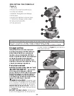
TO INSTALL BATTERY PACK:
Insert
battery pack (5) firmly into tool until an
audible click is heard
as shown in
Figure
B
. Ensure battery pack is fully seated and
fully latched into position.
TO REMOVE BATTERY PACK:
Depress
the battery release button (6) as shown in
Figure C
and pull battery pack out of tool.
Variable Speed Trigger Switch
The tool is turned ON and OFF by
squeezing and releasing the trigger switch
(1). The farther the trigger is depressed,
the higher the speed of the drill.
• To turn the tool on, squeeze the trigger
switch (1).
• To turn the tool off, release the trigger
switch. Your tool is equipped with a
brake. The chuck will stop as soon as
the trigger switch is fully released.
NOTE:
Continuous use in variable
speed range is not recommended. It
may damage the switch and should be
avoided.
Forward/Reverse Button
A forward/reverse control button (2)
determines the rotational direction of the
tool and also serves as a lock off button.
• To select forward rotation, release the
trigger switch and depress the forward/
reverse control button on the right side
of the tool.
• To select reverse, depress the forward/
reverse control button on the left side of
the tool.
• The center position of the control button
locks the tool in the off position. When
changing the position of the control
button, be sure the trigger is released.
QUICK RELEASE CHUCK-
FIGURES D AND E
NOTE:
The chuck accepts 1/4 inch
(6.35 mm) hex accessories only. Remove
battery pack before changing accessories.
TO INSTALL AN ACCESSORY
Firmly insert the accessory completely
into the quick release chuck (4) until an
audible click is heard as shown in
Figure
D
and verify the accessory is locked in
place by tugging on it.
8
D
4
C
B


