Page 8
EMHART TEKNOLOGIES
• 50 Shelton Technology Center, Shelton, CT 06484 • Tel. (877) EMHART1 • Fax: (800) 225-5614 •
www.emhart.com
Note:
Numbers in
bold type
refer to call out numbers in illustration.
SERVICING THE JAWS, JAW PUSHER AND JAW PUSHER SPRING
Regularly cleaning the Jaws and front end parts will prevent mandrels sticking in the Jaws and extend the life
of the Jaws.
1. Disassemble the tool front end as described above. Clean Jaws
3
using a brush and solvent. If jaw teeth
show significant wear replace both jaws.
2. Check Jaw Pusher Spring
5
for fatigue. A new spring measures 2-1/8" (54mm) in length. Replace spring if
shorter than 1-7/8" (46mm).
3. Thoroughly clean the inside of the Jaw Guide
11
, Nose Housing
44
, the Jaw Pusher
22
and wipe out or blow
out debris from around other exposed parts.
4. Lightly oil Jaws
3
and Jaw pusher
22
before reassembling.
5. Reassemble parts in reverse order tightening Jaw Guide
11
, Nose Housing
44
and Nosepiece
12
to torque
specifications in Table 1.
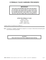
REPLENISHMENT OF HYDRAULIC FLUID
A shortened stroke indicates minor hydraulic fluid loss. Small amounts of fluid can be replaced without
disassembling the tool.
Equipment Needed:
Oil Replacement Screw, 3/8" - 24 Socket Head Cap Screw
Large slotted screwdriver
Hydraulic Fluid
Soft jawed vise
7/16" (11mm) open end wrench
Procedure
1. Place the tool in a soft-jaw vise, making sure the Fill Screw
10
is point-
ing up.
2. Remove the Nosepiece
12
, the Fill Screw
10
and Seal Washer
4
.
3. Screw the Oil Replacement Screw into the Nose Housing where the
Nosepiece
12
was removed. Tighten only until resistance is felt.
4. To properly add fluid, the Hydraulic Piston
26
must be pushed back. To
do this,
simultaneously turn the Oil Replacement Screw into the Nose
Housing (approximately 8-10 turns of the screw) while adding the oil
one drop at a time through the Fill Screw opening. Do not tighten the
Oil Replacement Screw since internal tool damage may result.
5. Allow bubbles to rise out of the oil and top off if necessary.
6. Reinstall Fill Screw
10
and Seal Washer
4
. Tighten securely. For torque
specifications see Table 1.
7. Remove the Oil Replacement Screw. Replace the Nosepiece
12
and
tighten securely.
8. Reconnect the air supply.
9. Loosen Fill Screw
10
very slightly, allowing excess oil to be forced out.
10. Wipe tool clean and tighten Fill Screw
10
to torque specifications in Table 1.
If oil loss is rapid or excessive, refer to the service manual for seal replacement procedures.
Caution:
The tool must be disconnected from the air supply before attempting
to replenish hydraulic fluid.
Caution:
Do not depress the trigger when Fill Screw 10 is loose. This will
cause oil to be forced out under great pressure.
MADE IN
U.S
.A.


