Workbook 4
Controller SIGMATEK - Boiler control
2
CONTENT
1
USE AND ADVANTAGES....................................................................................................................................... 3
2
3. INSTALLATION INSTRUCTIONS ....................................................................................................................... 3
2.1
CONTROL UNIT............................................................................................................................................ 4
2.1.1
Boiler Function Module HZS 521-G ...................................................................................................... 5
2.1.1.1
Technical base data ........................................................................................................................ 7
2.1.2
Terminal HZS 555-S with USB ............................................................................................................. 8
2.1.2.1
Technical data ................................................................................................................................ 8
2.2
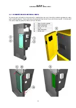
CONNECTION OF ELECTRICAL PARTS ......................................................................................................... 10
3
CONTROL UNIT OPERATION ............................................................................................................................. 12
3.1
MAIN MENU ............................................................................................................................................... 12
3.2
OPERATING CONDITIONS – MAIN MENU..................................................................................................... 13
3.3
MAIN MENU ............................................................................................................................................... 14
3.3.1
Setting menu ................................................................................................................................... 14
3.3.1.1
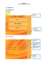
Info menu .................................................................................................................................... 14
3.3.1.2
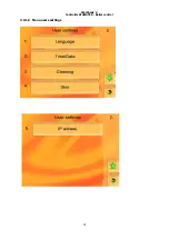
Menu users settings ...................................................................................................................... 15
3.3.1.3
Menu Service ................................................................................................................................ 18
3.3.2
Menu – heating circuits..................................................................................................................... 28
3.3.2.1
Tank ............................................................................................................................................ 29
3.3.2.2
Sanitary water .............................................................................................................................. 31
3.3.2.3
Heating circuit .............................................................................................................................. 33
4
GUARANTEE AND LIABILITY FOR DEFECTS ........................................................................................................ 36
5
DISPOSAL OF PRODUCT AFTER TEH END OF ITS SERVICE LIFE.......................................................................... 36
PICTURES
Picture No. 1
Control unit - configuration ................................................................................................... 4
Picture No. 2
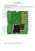
HZS 521-G Connector and terminal electronics layout ......................................................... 5
Picture No. 3
Module HZS 532-1 ................................................................................................................. 6
Picture No. 4
Other modules ....................................................................................................................... 6
Picture No. 5
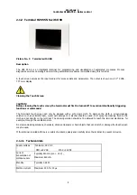
Terminal with USB ................................................................................................................. 8
Picture No. 6
Main menu – sample of visualisation .................................................................................. 12
Picture No. 7
Circuit diagram – control unit.............................................................................................. 37
Picture No. 8
Circuit d module HZS 533 ..................................................................................... 38
Picture No. 9
Circuit diagram - HZS 533, HZS 535 .................................................................................... 39
Содержание Sigmatek
Страница 1: ......
Страница 16: ...Workbook 4 Controller SIGMATEK Boiler control 15 3 3 1 2 Menu users settings ...
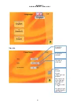
Страница 18: ...Workbook 4 Controller SIGMATEK Boiler control 17 Cleaning an ash removing Skin Time window setting ...
Страница 21: ...Workbook 4 Controller SIGMATEK Boiler control 20 Actual values Configuration ...
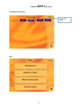
Страница 27: ...Workbook 4 Controller SIGMATEK Boiler control 26 Cleaning Ash removing USB Time window setting ...
Страница 28: ...Workbook 4 Controller SIGMATEK Boiler control 27 Load from USB Save on USB ...
Страница 33: ...Workbook 4 Controller SIGMATEK Boiler control 32 ...
Страница 35: ...Workbook 4 Controller SIGMATEK Boiler control 34 ...
Страница 36: ...Workbook 4 Controller SIGMATEK Boiler control 35 i ...
Страница 38: ...37 Picture No 7 Circuit diagram control unit ...
Страница 39: ...38 Picture No 8 Circuit diagram module HZS 533 ...
Страница 40: ...39 Picture No 9 Circuit diagram HZS 533 HZS 53 ...

