background image


31 

Table 7.11: Solutions for Troubles #11 

Possible Reasons 

Solutions


Low battery. 

Charge the battery. 

8. Emergency Situations 

(1) Leaking Batteries 

If  the  battery  pack  leaks  electrolyte,  avoid  contact  with  the  leaking  liquid  or 

gas.  If  one  is  exposed  to  the  leaked  substance,  immediately  perform  the 

actions described below. 

Inhalation: Evacuate the contaminated area, and seek medical attention. 

Contact  with  eyes:  Rinse  eyes  with  flowing  water  for  15  minutes,  and  seek 

medical attention. 

Contact  with  skin:  Wash  the  affected  area  thoroughly  with  soap  and  water, 

and seek medical attention. 

Ingestion: Induce vomiting, and seek medical attention. 

(2) Fire 

NO WATER! Only dry powder fire extinguisher can be used; if possible, move 

the battery pack to a safe area before it catches fire. 

(3) Wet Batteries 

If the battery pack is wet or submerged in water, do not let people access it, 

and then contact POMCube or an authorized dealer for technical support. 

(4) Damaged Batteries 

Damaged batteries are dangerous and must be handled with the utmost care. 

They are not fit for use and may pose a danger to people or property. If the 

battery pack seems to be damaged, pack it in its original container, and then 

return it to POMCube or an authorized dealer. 

NOTE: 

Damaged batteries may leak electrolyte or produce flammable gas. If 

such damage occurs, please contact POMCube. 


Содержание iCAN NetZero PNZ-BES1-5K

Страница 1: ...iCAN NetZero User Manual Intelligent Energy System ICN2V1 0 0 ...

Страница 2: ......

Страница 3: ...5 4 2 Specification 5 4 3 Parts and Functions 7 5 Installation 15 5 1 Tools and Safety Gear 15 5 2 Assemble the Rack 16 5 3 Install the Modules 17 5 4 Internal Wiring 19 5 5 External Wiring 21 6 Basic Operations 26 6 1 Boot System 26 6 2 Shut Down System 26 6 3 Getting Started with NetZero App 27 6 4 Network Connection 27 6 5 Reset Network 28 7 Troubleshooting 28 8 Emergency Situations 31 9 Warran...

Страница 4: ...kind This document and all information discussed herein remain the sole and exclusive property of POMCube NetZero system may be updated for technical reasons without prior notice Purchasing this product indicates that you have acknowledged it and accepted it 2 Legal Compliance 2 1 Disposal and Recycling This symbol on the product or on its packaging indicates that this product must not be disposed...

Страница 5: ...ital device pursuant to Part 15 of the FCC Rules These limits are designed to provide reasonable protection against harmful interference in a residential installation This equipment generates uses and can radiate radio frequency energy and if not installed and used in accordance with the instructions may cause harmful interference to radio communications However there is no guarantee that interfer...

Страница 6: ... or if it shows any kind of visible damage 4 Do not handle the device and its components with wet hands Failure to observe this may result in electric shocks 5 Do not dismantle the device 6 Do not damage any of the cable Do not place it near any hot objects bend it excessively twist it pull it or wrap it into a bundle 7 Shut down the device and switch off all the external input and output switches...

Страница 7: ...t you clean the device by wiping it gently using a soft and dry cloth Do not use water chemical substances or detergents These may cause discoloration or corrosion to the product s exterior and may cause a fire or electric shock Do not attempt to repair the device or its accessories by yourself as damage or personal injury may occur Damage caused by unauthorized repair is not under the warranty Pl...

Страница 8: ...s to eliminate the reliance of conventional power produced from fossil energy and maximize the use of clean energy whether they are locally generated or from the grid 4 2 Specification Table 4 2 1 Specification Model No PNZ BES1 5K Grid Generator Voltage 90 140V Frequency 60 5Hz Current Max 63A Load Power 5 0kVA Frequency 60Hz Voltage 110 120 127V Configurable Overload Cap 120 3s 150 0 15s Battery...

Страница 9: ...D 1610 570 510mm 63 4 22 4 20 1in Weight 3 Max 360kg 794lbs Operating Environment Temperature 41 104 F 5 40 C Humidity 10 90 No Condensation Split Phase Supported by 2 Systems in Parallel Model No PNZ GDS1 7K Grid Generator Voltage 190 280V Frequency 60 5Hz Current Max 32A Load Power 7 0kVA Frequency 60Hz Voltage 220 240V Configurable Overload Cap 120 3s 150 0 15s Battery Module Spec 102 4V 54Ah M...

Страница 10: ...F 5 40 C Humidity 10 90 No Condensation Split Phase Supported by Autotransformer NOTE 1 The actual battery DoD Depth of Discharge is at 80 2 It is recommended Vmpp NOCT Nominal Operating Cell Temperature of solar panel string should be within this range Refer to solar panel datasheet for the value of Vmpp at NOCT condition 3 Slight weight deviation for each device 4 3 Parts and Functions NOTE The ...

Страница 11: ... Air Deflector Cable Bracket and Cover Plate 2 EMS Module Manage the whole system 3 PCS Module Convert the power from AC to DC or from DC to AC 4 Solar Controller Track the Max Power Point of solar power charge the battery power the load 5 BCMS Module Manage and protect all battery modules 6 Battery Module Store electric energy 1 2 3 4 5 6 ...

Страница 12: ...dicate the device status and the network status Solid red System startup in progress Blinking red Ready for network connection Blinking green Wi Fi network and password detected connecting to router If it blinks for over 3minutes either the network or the password might be incorrect Solid white Connecting to the Internet or troubles in Internet connection while the router DC 12V 1 2 3 4 ON DIP ADD...

Страница 13: ...cation timeout as below EMS module PCS module Solar controller BCMS module Blinking indicate system fault as below ADD Reserved Dry Contact NC1 COM1 Stop generator Others Reserved PV Communicate with solar controller RS232 For the manufacturer s debugging PCS Communicate with PCS module RS485 2 Reserved RJ45 port follow RS485 protocol RS485 1 For the manufacturer s debugging BCMS Communicate with ...

Страница 14: ...upply Status Indicate the power supply status On Normal Off No power MAIN Load output switch BAT Battery bus connect to Solar Controller Generator Start and Stop START A START B Start generator STOP A STOP B Stop generator Synchronizing Signal Reserved DC 12V DC12V power supply output EMS Communicate with EMS module EMS CAN MAIN GND SYN START A START B STOP A STOP B DC 12V GRID GEN LOAD DC 12V DC ...

Страница 15: ... ADD 1 3 4 up 4 Solar Controller Figure 4 3 4 Solar Controller Front View Table 4 3 4 Solar Controller Parts Parts Functions PV Input PV1 Solar power input negative 1 PV1 Solar power input positive 1 PV2 Solar power input negative 2 PV2 Solar power input positive 2 PV SWITCH Solar power input switch DC 12V DC12V power supply output RS485 Reserved EMS Communicate with EMS module STATUS Indicate the...

Страница 16: ...em RS232 For the manufacturer s debugging RS485 2 Reserved RJ45 port follow RS485 protocol RESET Reset BCMS module RS485 1 Communicate with other BCMS module EMS Communicate with EMS module STATUS Indicate BCMS module status Blinking blue Boot up in progress Blinking green Self inspecting Solid green Working normally STATUS SOC EMS RS485 1 START RS485 2 RS232 1 2 3 4 ON DIP ADD NO1 COM1 COM2 D11 D...

Страница 17: ...nce under system charging and discharging ADD Reserved Dry Contact Reserved LINK PORT Communicate with Battery Module DC 12V DC12V power supply input 6 Battery Module Figure 4 3 6 Battery Front View 102 4V 54Ah Figure 4 3 7 Battery Front View 51 2V 108Ah B B LINK PORT0 RS232 STATUS LINK PORT1 LINK PORT0 RS232 STATUS LINK PORT1 B B LINK PORT0 RS232 STATUS LINK PORT1 ...

Страница 18: ...d pink Alarming Solid red In device protection or troubles RS232 For the manufacturer s debugging LINK PORT0 Communicate with battery module LINK PORT1 Communicate with battery or BCMS module 5 Installation 5 1 Tools and Safety Gear NOTE It is recommended to use proper tools and wear safety gears when installing 1 Slotted Screw Driver 2 3mm Inner Hexagonal Screw Driver 3 Wire Cutter 4 Insulated Gl...

Страница 19: ...n Pay attention to the directions of the opening side of beams Figure 5 2 1 Put the Frames and Beams Together 2 Install the screws to fasten the frames and beams Figure 5 2 2 Install the Screws Beam 4pcs Left Side Frame Right Side Frame Opening Side of the Beams Screw M5 10 32pcs ...

Страница 20: ...maintenance space requirement for each side Figure 5 2 3 Place and Mount the Rack 5 3 Install the Modules 1 Put all the modules into the rack from the front side and then fasten them with screws Install the Cover Plate while the quantity of battery module is less than five 24in 600mm 40in 1000mm 4in 100mm 20in 500mm Front Side is with Threaded Holes on the Support Surface Maintenance Space ...

Страница 21: ...connector as the figure shown Figure 5 3 2 Screw on the Wi Fi Antenna 3 Put the air deflector onto the right side of the rack and then fasten the screws Figure 5 3 3 Install the Air Deflector Cover Plate Screw M5 10 4pcs module Screw M5 10 4pcs Air Deflector Wi Fi Antenna ...

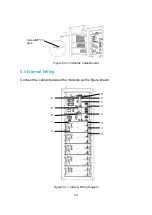
Страница 22: ...19 3 Figure 5 3 4 Install the Cable Bracket 5 4 Internal Wiring Connect the cables between the modules as the figure shown Figure 5 4 1 Internal Wiring Diagram 1 2 3 Screw M5 10 4pcs 3 4 5 4 4 6 7 8 8 8 ...

Страница 23: ... 140mm Standard 8 way Ethernet cable BCMS module Link Port to the top battery module Link Port1 Battery module Link Port0 to the next battery module Link Port1 below 5 Communication cable Black 240mm Standard 8 way Ethernet cable EMS module PCS port to PCS module EMS port 6 Communication cable Black 340mm Standard 8 way Ethernet cable EMS module PV port to Solar Controller EMS port 7 Communication...

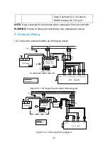
Страница 24: ...63A L N AC120V 2P 16A L N 2P 63A Generator L N NetZero 5KW 110 120 127V 63A ATS AC LOAD REMOTE CONTROL L N PE GND NETWORK PV Switch 2P 10A 2P 10A 2P 10A 2P 10A Router L N AC120V L N AC120V L N AC120V L N AC120V REMOTE CONTROL L N Grid Power Line Comm Line L1 L2 L1 L2 GND GND L1 L2 PV1 PV1 PV2 PV2 Solar Panel String 1 Solar Panel String 2 GRID GEN LOAD L1 L2 2P 32A Generator L1 L2 NetZero 7KW 220 2...

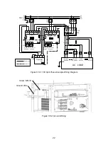
Страница 25: ... String 4 GRID GEN LOAD 3P 125A L1 L2 AC240V L1 L2 N N AC120V AC120V 2P 32A 2P 10A 2P 10A L1 N L2 2P 63A 2P 63A Generator L1 L2 N N NetZero 1 NetZero 2 1 2 3 4 ON DIP 1 2 3 4 ON DIP PV Switch CAN LINK1 RS485 1 LINK2 RS485 1 LINK2 NETWORK L1 L2 AC240V 2P 32A Router AC LOAD L1 L2 N L1 L2 N PE Power Line CAN LINK1 NETWORK PV Switch ADD ADD Comm Line GND REMOTE CONTROL REMOTE CONTROL REMOTE CONTROL Gr...

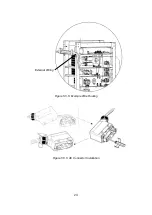
Страница 26: ...23 Figure 5 5 5 Example Wire Routing Figure 5 5 6 AC Connector Installation External Wiring ...

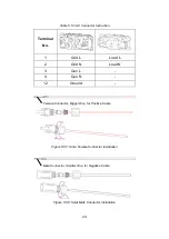
Страница 27: ... No 1 Grid L Load L 2 Grid N Load N 3 Gen L 4 Gen N 12 Ground Figure 5 5 7 Solar Female Connector Installation Figure 5 5 8 Solar Male Connector Installation Female Connector Bigger One for Positive Cable Male Connector Smaller One for Negative Cable ...

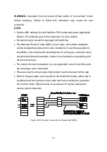
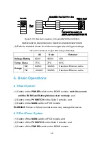
Страница 28: ...ion of electrical equipment Installation must comply with specifications for wire types conductor sizes electrical and thermal insulation branch circuit protection grounding and disconnect devices The actual connection depends on your application case Not all the ports are necessary to be connected Please set up the actual value of generator maximum power by the app Refer to the generator user man...

Страница 29: ...d Ethernet cable 7K 10AWG 12AWG Standard Ethernet cable 6 Basic Operations 6 1 Boot System 1 Switch on the POWER switch on the BCMS module wait 60 seconds until the BCMS and Battery Module start normally and 2 Switch on the PV SWITCH on the Solar Controller and 3 Switch on the MAIN switch on PCS module WARNING Failure to follow the instructions may damage the device 6 2 Shut Down System 1 Switch o...

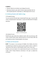
Страница 30: ...OS Eloncity App 2 Add New Devices Start Eloncity app and touch the add device button then scan the device QR code or input the device code to add your devices You can find the QR code and the device code on the label pasted on the device 6 4 Network Connection NOTE The network is not necessary for NetZero But NetZero should be connected to your router if you need to use the app to monitor it Inter...

Страница 31: ...eded to press the Reset Button It is not provided 7 Troubleshooting 1 The indicators on EMS modules are always solid red Table 7 1 Solutions for Troubles 1 Possible Reasons Solutions The device may be crashed or damaged Unplug power supply of DV12 on EMS and re plug in 5 seconds If it cannot recover shut it down and contact us 2 The indicators on EMS modules are always blinking red Table 7 2 Solut...

Страница 32: ...the router or Internet Check your internet status Reset the router if necessary 5 Failed to start the generator remotely Table 7 5 Solutions for Troubles 5 Possible Reasons Solutions The generator may not work properly Check the generator The remote control cable is disconnected Check and reconnect the cable 6 The indicator on BCMS module is solid red and the indicator on at least one battery modu...

Страница 33: ...8 Solutions for Troubles 8 Possible Reasons Solutions Voltage shortage of battery Charge the batteries immediately 9 The indicator on BCMS keeps blinking in green for over 1 minute Table 7 9 Solutions for Troubles 9 Possible Reasons Solutions BCMS fails in self inspection Reboot the system 10 The indicator on battery module keeps blinking in blue for over 30 seconds Table 7 10 Solutions for Troubl...

Страница 34: ...attention Ingestion Induce vomiting and seek medical attention 2 Fire NO WATER Only dry powder fire extinguisher can be used if possible move the battery pack to a safe area before it catches fire 3 Wet Batteries If the battery pack is wet or submerged in water do not let people access it and then contact POMCube or an authorized dealer for technical support 4 Damaged Batteries Damaged batteries a...

Страница 35: ...stated herein shall NOT apply if The product was not used in accordance with any accompanying instructions The product was not used for its intended function and environment Any failure or defect arose out of the presence of a third party product or component whether authorized or not Any failure or defect was a result of improper installation or testing misuse neglect unauthorized repair modifica...

Страница 36: ..._____________________________________________________________ 2019 POMCube Inc All rights reserved For more information please visit www pomcube com Follow us Facebook Twitter ESS4Residence POMCube Inc ...

Отзывы: