


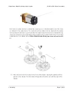


holes in the spacer plate should line up with the through-holes in the shield resting on top
of it, and the motor leads should be aligned so they pass through the slots in the spacer as
shown in the picture below. There is only one correct orientation for these plates. (The plate
consists of two separate pieces to make it possible to disassemble the Zumo without having
to desolder the motors or battery terminals.)
14. In each of the four mounting holes, insert a #2-56 machine screw through the shield, spacer
plate, and chassis, and tighten it against a nut under the chassis. It is usually easier to place
the nut into the recess first and hold it there with a finger or piece of tape while inserting the
screw. Note that the kit includes two different sizes of #2-56 machine screws: 1/4″and 5/16″.
The two longer screws are intended for use in the front holes (near the motors) if you are also
Pololu Zumo Shield for Arduino User’s Guide
© 2001–2019 Pololu Corporation
2. Assembly
Page 17 of 52


