background image

5. Getting Started

5.a. Installing Windows Drivers

If you use Windows XP, you will need to have either

Service Pack 3

[http://www.microsoft.com/

downloads/details.aspx?FamilyId=68C48DAD-BC34-40BE-8D85-6BB4F56F5110]

or Hotfix KB918365

installed before installing the drivers for the Orangutan SVP. Some users who installed the
hotfix have reported problems using the programmer which were solved by upgrading to
Service Pack 3, so we recommend Service Pack 3 over the hotfix.

Before you connect your Pololu Orangutan SVP robot controller to a computer running Microsoft
Windows, you must install its drivers:

1. Download and install the

Pololu AVR Development Bundle

[https://www.pololu.com/file-redirect/

avr-development-bundle]

(~6MB exe)

. This includes the drivers for the Orangutan SVP, along

with the Pololu AVR C/C++ Library and the drivers for the Pololu USB AVR Programmer.
If you are not sure which of these components you need, it is OK to install all of them.
If you only need to install the drivers for the Orangutan SVP, you can download those
separately:

Orangutan SVP Windows Drivers

[https://www.pololu.com/file/0J488/orangutan-svp-

win-121115.exe]

(53k exe).

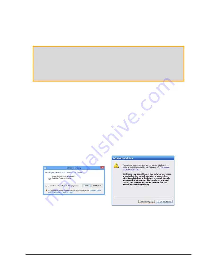
2. During the installation, Windows will ask you if you want to install the drivers. Click “Install”

(Windows 7, 8, and Vista) or “Continue Anyway” (Windows XP).

Windows 10, Windows 8, Windows 7, and Windows Vista users:

After the installation is complete,

your computer should automatically install the necessary drivers when you connect an Orangutan
SVP, in which case no further action from you is required.

Windows XP users:

After the installation is complete, follow steps 3-7 for each new Orangutan SVP

you connect to your computer.

Pololu Orangutan SVP User’s Guide

© 2001–2019 Pololu Corporation

5. Getting Started

Page 16 of 43

Содержание Orangutan SVP-1284

Страница 1: ...21 5 c Programming your Orangutan 22 5 d Assembling the kit version 22 6 AVR Pin Assignment Table Sorted by Function 27 7 AVR Pin Assignment Table Sorted by Pin 28 8 Using the USB Communication Port...

Страница 2: ...serves as an integrated AVR ISP programmer which means that no external programmer is required to use the Orangutan SVP This auxiliary processor provides a USB connection that allows direct communicat...

Страница 3: ...of which 8 can be analog inputs 4 input lines on the auxiliary processor which can be either 4 analog inputs or dual quadrature encoder inputs 2 hardware UARTs Removable 16 character 2 line LCD with b...

Страница 4: ...TL level serial devices from a computer In Linux the three virtual COM ports created by the SVP should appear as devices with names like dev ttyACM0 dev ttyACM1 and dev ttyACM2 the numbers depends on...

Страница 5: ...utan SVP from working with macOS 10 11 or later Note You may not need to use the Orangutan SVP s USB connection If you have an AVR ISP programmer then you can program the AVR on the Orangutan SVP by c...

Страница 6: ...and an assortment of sample code in the Pololu AVR Library https www pololu com docs 0J20 We would be delighted to hear from you about any of your projects and about your experience with the Orangutan...

Страница 7: ...ams of the Orangutan SVP are available here Orangutan SVP schematic diagram https www pololu com file 0J265 org06a02_schematic pdf 99k pdf Pololu Orangutan SVP User s Guide 2001 2019 Pololu Corporatio...

Страница 8: ...ditional input lines The auxiliary processor also serves as a programmer for the main processor meaning that an external programmer is not required but you can use one if you want to The auxiliary pro...

Страница 9: ...ous 2 A and can briefly deliver up to 6 A If you are not taking extra steps to keep the motor driver cool such as using a heat sink exceeding this continuous current rating for too long will cause the...

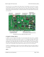
Страница 10: ...the four 4 3 0 100 female headers along the lower edger of the board as shown below Each I O line has associated power and ground connections for easy connections to sensors the exterior bottom pin is...

Страница 11: ...care of configuring the pins as inputs enabling the AVR s internal pull up resistors and debouncing accounting for the fact that pushbuttons physically bounce when pressed Buzzer The Orangutan SVP com...

Страница 12: ...d to do different things They can function as three analog inputs plus a serial receive line as four analog inputs or as the inputs for two quadrature encoders See the OrangutanSVP https www pololu co...

Страница 13: ...Both regulators can supply a current of 3 A The adjustable voltage regulator draws current from the external power supply and produces an output voltage called VADJ The trimmer potentiometer in the up...

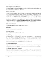
Страница 14: ...the serial transmit line for UART0 TXD0 the LED will flicker whenever serial data is being transmitted from the AVR The LED can be disconnected from PD1 by cutting a labeled trace PD1 LED on the bott...

Страница 15: ...uxiliary processor s TX line This LED is tied to the TX line so it will flicker whenever the auxiliary processor is transmitting TTL level serial bytes from the computer This LED will also blink when...

Страница 16: ...ith the Pololu AVR C C Library and the drivers for the Pololu USB AVR Programmer If you are not sure which of these components you need it is OK to install all of them If you only need to install the...

Страница 17: ...Hardware Wizard three times Each time the Found New Hardware Wizard pops up follow steps 4 7 4 When the Found New Hardware Wizard is displayed select No not this time and click Next 5 On the second sc...

Страница 18: ...lick Continue Anyway 7 When you have finished the Found New Hardware Wizard click Finish After that another wizard will pop up You will see a total of three wizards when plugging in the Orangutan SVP...

Страница 19: ...loads details aspx FamilyId 68C48DAD BC34 40BE 8D85 6BB4F56F5110 or Hotfix KB918365 Some users who installed the hotfix have reported problems using the programmer which were solved by upgrading to Se...

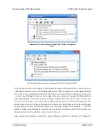
Страница 20: ...ndows 10 and later and it will display USB Serial Device as the name for each port The ports will be usable but it will be hard to distinguish the ports from each other because of the generic name sho...

Страница 21: ...to exit one of the demos There are nine demos accessible from the menu 1 Analog Inputs This demo displays voltage readings from the Orangutan SVP s 13 analog inputs as a bar graph The inputs are in th...

Страница 22: ...the state of the RTS handshaking line The source code for the demo program is included with the Pololu AVR C C Library https www pololu com docs 0J20 in the examples atmega324p svp demo program or exa...

Страница 23: ...uded box header https www pololu com product 854 One 2 8 shrouded box header https www pololu com product 898 One buzzer Five pushbuttons https www pololu com product 1400 One 2 20 breakaway male head...

Страница 24: ...location 2 Power input There are two parallel connection points provided for the 6 13 5V power input You can install a 3 5mm terminal block on the large holes to accommodate large wires You can also i...

Страница 25: ...d in at this location 8 Buzzer The buzzer can be soldered in at this location 9 Reset buttons A reset pushbutton can be soldered in at this location 10 SPI Programming connector The assembled version...

Страница 26: ...emale headers you can use instead 16 Servo power selection To use your servo ports you will need to connect a power source no power source is connected by default You can install two 1 3 male headers...

Страница 27: ...trol RS R W E PB0 PB1 PB2 LCD data 4 bit DB4 DB7 PC2 PC5 SPI auxiliary processor control lines x3 PB5 PB6 PB7 ICSP programming lines x3 PB5 PB6 PB7 ADC reference pin AREF reset pushbutton RESET Using...

Страница 28: ...t B Pins Orangutan Function Notes Alternate Functions PB1 LCD control line R W Divided system clock output CLKO Timer Counter 1 External Counter Input T1 PB2 LCD control line E External interrupt 2 IN...

Страница 29: ...replaced with jumper USART0 output pin TXD0 PD2 digital I O USART1 input pin RXD1 External interrupt 0 INT0 PD3 digital I O USART1 output pin TXD1 External interrupt 1 INT1 PD4 buzzer Timer1 PWM outpu...

Страница 30: ...the auxiliary processor so we recommend using it as a digital output See Section 3 j of the Pololu USB AVR C C User s Guide for more information Pololu Orangutan SVP User s Guide 2001 2019 Pololu Corp...

Страница 31: ...ram is connected to the Orangutan and make the Orangutan s behavior dependent on that On the PC side the Orangutan SVP s USB drivers make the USB Communication port look like a standard serial port to...

Страница 32: ...driver to create virtual serial ports at the time the Orangutan SVP is plugged in To determine the port name in Mac OS X type ls dev tty usb There should be three entries for the Orangutan SVP and th...

Страница 33: ...B Communication Port 1 2 3 4 5 6 7 8 9 10 11 12 13 14 15 16 17 18 19 20 21 22 23 24 25 Choose the port name and baud rate Port Name must be determined from the Device Manager Baud rate is irrelevant f...

Страница 34: ...gh level overview can be found in Section 3 j of the Pololu AVR C C Library User s Guide https www pololu com docs 0J20 The Serial Port Communication section of the library provides many functions for...

Страница 35: ...and one stop bit 8N1 To use the TTL Serial Port you must first determine what port name the operating system has assigned it To determine the port name in Microsoft Windows open the Device Manager exp...

Страница 36: ...Br y Terminal http sites google com site terminalbpp Windows To use any of these terminal programs you must specify the port name determined above and the baud rate PuTTY is a free Windows terminal p...

Страница 37: ...ect to the port port Open Transmit two bytes 0x61 0x62 port Write new byte 0x61 0x62 0 2 Wait for a byte to be received on the RX line int response port ReadByte Show the user what byte was received M...

Страница 38: ...e OC2B and PC6 Pins PD6 and PD7 are connected to the AVR s eight bit hardware PWM outputs which allows you to achieve variable motor speeds through hardware timers rather than software This frees the...

Страница 39: ...conduct current backwards resulting in a VBAT around 4 6 5 0 V and a VCC around 4 3 4 6 V In some cases VCC will be low enough to trigger brown out detection on the AVR Therefore if you are having tro...

Страница 40: ...indows computer 1 Connect the Orangutan SVP to your computer via USB 2 Open up the Device Manager 3 Double click on the Pololu Orangutan SVP Programmer entry in the Ports COM LPT list 4 In the Details...

Страница 41: ...y places on the SVP check the Orangutan SVP Reference Diagram https www pololu com file 0J244 orangutan_svp_reference_diagram pdf 82k pdf if you are not sure where to find ground You may have to remov...

Страница 42: ...ds erasing the current firmware and then it will echo back an upper case S Do not disconnect the device from the computer after this point until the upgrade is complete 10 Now send the contents of the...

Страница 43: ...ps www pololu com docs 0J20 instructions on installing and using the library as well as sample programs Atmel Studio 7 https www microchip com avr support atmel studio 7 free development IDE from Atme...

Отзывы: