

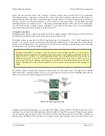


Lastly, you can use both motor 1 and 2 outputs to control a single, more powerful (up to 25 A continuous)
bidirectional motor by connecting it as shown above. One of the motor’s terminals connects to both of motor 1’s
outputs while the other of the motor’s terminals connects to both of motor 2’s outputs. In order to use your TReX in
this way, you must use the serial interface to set the TReX to “joint motor mode”. In this mode, the single
bidirectional motor is considered “motor 1”. The motor speed/direction indicator LEDs will not work in this mode,
nor will current sensing or channel mixing. Although it is not shown in the figure above, you can additionally
control an auxiliary motor while running in “joint motor mode”.
3.b. Signal Connections
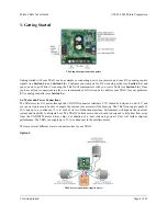
RC/analog signals should connect to the interior of the three channel columns, which are located on the left side of
the board; this connection is represented by the white wire in the figure below.
The middle column is connected to the TReX’s regulated power (Vcc) through the ”+=Vcc” (BEC) jumper and will
provide 5 V to your RC receiver or analog controller when this jumper in place. This connection is represented by
the red wire in the figure below. If you want to power your RC receiver or analog controller from a source other than
the TReX, make sure you remove the BEC jumper.
Warning:
This middle Vcc column is tied to the output of a linear voltage regulator, so current output is
limited by thermal dissipation. The regulator will only be able to safely supply a maximum of 100 mA
when VIN is 16 V (it has a 1-W power dissipation rating). This is typically sufficient for powering an
analog joystick or RC receiver, but it is insufficient for powering servos. If you want to connect servos to
some of your RC receiver channels, you must power your RC receiver separately and disconnect the BEC
jumper. Attempting to use the TReX’s regulated Vcc line to power servos can permanently damage the
TReX.
The exterior column is ground and is represented by the black wire in the figure below. Your input source and the
TReX must share a common ground, even if you are powering your input source from something other than the
TReX. You only need to make a single ground connection.
TReX RC/serial input signal connections
In addition to RC/analog connections, you can connect the TReX to either an RS-232 (COM) or logic-level (TTL)
serial port. Note that you should not simultaneously have both RS-232 and TTL connected. The figure above depicts
the two possible serial connections. The serial pins are labeled from the perspective of the TReX, meaning you
should connect the TReX’s TX or SO line to your target’s receive line (the green wire in the figure above); your
Pololu TReX User's Guide
© 2001–2009 Pololu Corporation
3. Getting Started
Page 6 of 22


