13
SADRIN WS SMA
POLITEC | INSTALLATION MANUAL - VER.2.1
8.3 Expansion board wiring
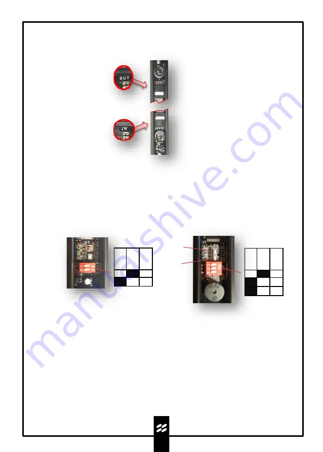
If inserting or removing expansion boards, make sure they are connected in the correct direction.
9.Programming and commissioning
9.1 Powering the barriers
Connect the power supply to the dedicated input respecting the polarity and check the flashing of the
LED.Power first the TX column and then the RX column.
9.2 Checking alignment and operation
DL1
RED LED
DL2
BLUE LED
TX
RX
O
FF
ON
1
2
3
O
FF
ON
1
2
1.
Set the TEST DIP 1 of the TX motherboard to ON.
2.
Set the TEST DIP 1 of the RX motherboard to ON.
3.
In this phase, the barrier alignment takes place, where each RX optic receives the signal from
the corresponding TX optic, the maximum value is reached when the BLUE test LED and the
buzzer provide a continuous signal.
4.
To exit the test, set TEST DIP 1 to OFF on the RX, the RED LED will flash and the WALK TEST
function will activate for a duration of 30'', the barrier will emit a continuous acoustic signal in
the event of interruption of one beam (two beams if configured in AND) to indicate the correct
operation of all optics.The BLUE LED will flash if the tampers are open.
5.
At the end of this phase, the BLUE TEST LED will light up and the RED LED will flash until the
TEST DIP 1 on the TX motherboard is set to OFF.
Expansion boards codes:
SADRIN ESP WS RX/SADRIN ESP WS TX


