Politec MANA MW Скачать руководство пользователя страница 17

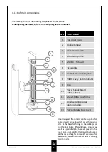
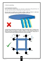
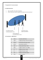
14.Barrier alignment

17

POLITEC | INSTALLATION MANUAL - VER.3.1

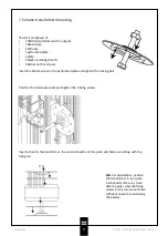
For a correct alignment, once the barriers have been installed, it is necessary to orient the
transmitting column in the direction of the receiving column, as precise as possible, as it is not
possible to make horizontal movements but only vertical corrections with the dish
antenna.Permanently fix the columns after performing the following steps:
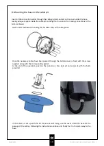
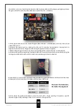
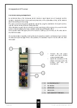
MANA MW 

1.Activate the cavities by setting the DIP on the back of each dish to OFF.This DIP must always remain
in this position.

2.Select the same synchronisation channel, on the 4 DIP unit on the MW TX board and on the MW RX
board

RX

TX

Содержание MANA MW

Страница 1: ...PRODUCT MANA MANA MW Product code MANA MW K BAND MICROWAVE PERIMETER PROTECTION BARRIER INSTALLATION AND MOUNTING MANUAL VERSION 3 0...

Страница 2: ...and installation 6 2 Cable pit positioning 7 Column transformer mounting 9 8 Column power supply connection 10 9 Evaluations before installation 11 9 1 Introduction to barriers 10 Barrier positioning...

Страница 3: ...g column which create an intrusion proof area This barrier is ideal for perimeter protection of internal and external areas It is equipped with a system for selecting the operating frequency that allo...

Страница 4: ...here is no warranty for the end user who in the event of breakdowns or faults must contact the installer or dealer The warranty excludes aesthetic parts as well as parts subject to normal wear and par...

Страница 5: ...illuminator 9 Dish 10 Power Supply board 12Vdc 24Vac 11 Mana 160VA transformer 12 Anodised anticorodal aluminium disc 13 Polycarbonate black cover 2 3 5 4 1 6 8 10 9 7 11 12 13 Upon request the colum...

Страница 6: ...els with universal circuit board housing insert and connect the radio transmitter and connect it to the barrier receiver board c Power up the barriers and program them d Test barrier operation e Place...

Страница 7: ...allation Insert the edge shown in the figure into the slot on the other wall and fix everything with the screws Insert the third side in the same way and tighten the screws Widen the two opposite wall...

Страница 8: ...ng Positioning must take place perpendicular to the ground If the base is not perfectly level minor adjustments can be made by adjusting the inserts on the cable pit By loosening the insert on the app...

Страница 9: ...1 plate 2 black insulating sheath 4 barrier anchor screws Insert the 60mm screw in the perforated plate and tighten the locking bolt Insert a sheath the transformer the second sheath and the plate an...

Страница 10: ...the base with sealing OR for cable entry with cable glands Once the necessary cables have been passed through the bottom cover is fixed with the screws supplied along with the corresponding gasket At...

Страница 11: ...INSTALLATION MANUAL VER 3 1 9 Column power supply connection FUSE A 5A 24Vac FUSE B 0 8A 13 8Vac Red Red Black Black Blue Brown brown blue black black red red Make all the electrical connections as sh...

Страница 12: ...width of which in the centre reaches up to 4 5m The most peripheral part is called the SENSITIVE ZONE while the most central part is called the ALARM ZONE View from above Signal interruption ALARM Whe...

Страница 13: ...s and fences to avoid wave reflections that would cause abnormal operation with generation of alarms MANA MW It should also be considered that due to the effect of the generated lobe there is a dead z...

Страница 14: ...x1 5 mm supplies the transformer with 230Vac The second which must beSHIELDED e g Nx0 22 mm minimum to transfer all the output signals of the individual columns to the alarm control unit N B The shiel...

Страница 15: ...the transformer 3 4 13 8 Vdc output Infrared section power supply 5 6 24 Vac input Cable coming out of the transformer 7 8 24 Vac output Heater power supply 13 Connections to the MANA AL 214 power sup...

Страница 16: ...ng limit is 0 25 A 5 Heater fuse Time delay 5 A to protect the heating circuits 6 Circuit fuse 0 8 A time delay to protect the MW TX or RX and IR circuits 7 Jumper J7 If inserted the 24Vac output of t...

Страница 17: ...ise as possible as it is not possible to make horizontal movements but only vertical corrections with the dish antenna Permanently fix the columns after performing the following steps MANA MW 1 Activa...

Страница 18: ...n again to have only the red and yellow LEDs on Gain trimmer Anticlockwise 8 Increase the signal level again by rotating the RX and TX columns horizontally and vertically using the locking screw behin...

Страница 19: ...alarms Low risk of non detection DLY Turn clockwise to decrease system sensitivity High requires a large mass to generate alarm Low requires a small mass to generate alarm 15 Basic functions 15 1 Bas...

Страница 20: ...immediate vicinity of the columns both transmitting and receiving This area is up to 5m long and is generally covered by using the installation of crossed columns near the corners of the perimeter to...

Страница 21: ...disturbance Intermittent buzzer sound Disturbance absent Buzzer sound absent 17 2 Function DIP MW RX board 1 LEDS It activates the LED bars 2 FIELD It displays the signal value on the LED bar 3 OPEN I...

Страница 22: ...ly with OUT 12Vdc and 24Vac HEATERS 24 Vac from internal power supply SENSITIVITY ADJUSTMENT ON BOARD alarm threshold mass detection CIRCUIT CONSUMPTION 100 mA OUTPUTS Alarm relay with NC clean contac...

Страница 23: ...y adjust the sensitivity appropriately Adjust the delay to avoid false alarms caused by animals I can t align Check that there are no obstacles of any kind interposed between RX and TX and that the co...

Страница 24: ...oducts governed by regulations in force in your area Warning Some parts of the products may contain polluting or dangerous substances which if dispersed in the environment could result in harmful effe...

Отзывы: