background image

Rechargeable battery (option)

Independent antenna (option)

This element is incompatible with solar power supply.

The antenna is connected to terminals 1 and 2  

(blue label „ANT”) of the control module: the 

conductor core to terminal 1; the stranded aerial  

wire to terminal 2.

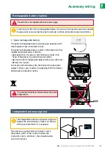
The spare rechargeable battery ensures gate operation with 

small speed in case of an electric fault.
The spare rechargeable battery is built in the electronic drive 

module and connected to it directly.

•  

Operation time: 10 cycles in the continuous mode or 24 

hours if the gate is in good technical condition.

•  

Optimum time of charging the battery before use: 48 hours.

•  

Battery life: 3 years.

To ensure optimum battery life, disconnect the gate power 

supply 3 times a year to allow its supplying from the battery 

during several operation cycles.


Spare rechargeable battery

ON/OFF

AUTO

PROG

ON/OFF

AUTO

PROG

NO!

Do not locate the battery conductor above the power 

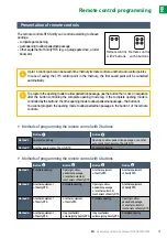
supply source.

35

EN

 - Assembly and service manual for EASY WAY202

EN

Accessory wiring 

Accessory wiring

To prolong the life of the rechargeable battery, the wire control systems are disconnected; 

the gate control is provided only by the remote controls and control radio transmitters.

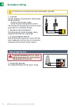
The independent antenna of greater range can 

replace the wire antenna. Locate it on the top 

of the post and check if it is exposed.

Содержание EASY WAY202

Страница 1: ...www polargos pl AUTOMATIC GATE EASY WAY202 EN Assembly and service manual ...

Страница 2: ...ts M8 x 40 mm or M8 x 70 mm M6 x 40 mm M8 x 85 mm the carriage bolt is designed for gate as sembly on steel posts 70 x 70 mm in case of gate assembly on steel posts 100 x 100 mm 8 sets of carriage bolts M8 x 120 mm willberequired 2 EN Assembly and service manual for EASY WAY202 EN AUTOMATIC GATE EASY WAY202 ...

Страница 3: ...23 Start up and standard use 25 Stages 25 Explanation of symbols 25 Remote control programming 25 Remote control operation 25 Switching on the system power supply 26 Automatic learning of the gate moving course 26 Setting the stand by activation mode of the electronic control system 27 Complete gate opening closing 27 Obstacle detection 27 Training for users 27 Advanced settings 28 Opening to allo...

Страница 4: ... at home and abroad The Company s purpose is to supply the market with the products that fulfil the highest standards of workmanship and meet customers expectations as regards aesthetics and fashion prevailing at the fence market Thank you for your confidence and choice of the device EASY WAY 202 Please read this manual thoroughly before assembly TECHNICAL ASSISTANCE HOTLINE 0 801 377 199 a charge...

Страница 5: ...installation check if the driven part is in good technical condition correctly balanced and if it opens and closes properly Show concern for maintenance of suitable distance from the zone between the driven partandfixedelementsinthevicinityinviewofdangercausedbymovementofthedriven part during opening crushing cutting jamming Inspect the gate visually during its movement All switches without interl...

Страница 6: ...ts Danger of death Nevertheless if such situation occurs consult a doctor immediately or go to hospital Be careful to avoid battery short circuit Do not throw batteries into fire or recharge them Risk of explosion occurs Hereby POLARGOS declares that the product described in this manual if it is used according to the given recommendations conforms to the basic requirements of European Directives i...

Страница 7: ... mm between the lower part of the leaves and the substrate Solution Obstacle detection system inside the drive If there is a risk of user confinement in the zone between the gate leaves and fixed elements in the vicinity leave a minimum distance of 50 cm between the leaves and the fixed elements Solution If there is a cutting zone in the system leave a minimum distance of 10cm between the leaf and...

Страница 8: ...rotection level IP 44 Built in radio wave receiver Yes Remote controls Radio frequency 433 42 MHz Operational range 30 m Number of memory settings 16 Possible connections Orange light output Flashing 24 V 10 W Zone lighting output the powered terminal max 500 W przy 230 V max 24 V 25 W for the solar system Accessory supply output 24 Vdc 200 mA Spare battery input Yes only at 230V Photocell input Y...

Страница 9: ...m Maximum opening angle for hinges fastened on the post side The opening angle of the gate should be within the range of 85 95 The opening angle of the both gate leaves should be the same The opening angle must be set by means of stops fastened to the substrate The stops are not included in the delivery 95o 95 o 9 5 o Product presentation The motor stops automatically at its internal limiter To st...

Страница 10: ... necessary to ensure proper corner set back and fastening Set stops at the desired opening angle of the gate The angle should be within the range of 85 95 Theopeningangleofthebothleavesshouldbethesame α α Theopeningstopisnotincludedinthedelivery The opening stop is not included in the delivery Opening stop is not included in the delivery Preparation for assembly 10 EN Assembly and service manual f...

Страница 11: ...en ended spanner 13 open ended spanner 17 tubular spanner 13 i 10 distribution box flat screwdriver hammer pincers skinning pliers cross headed screwdriver level 13 13 13 10 13 10 10 5 7 5 6 5 Preparation for assembly 17 11 EN Assembly and service manual for EASY WAY202 EN ...

Страница 12: ...thesupplyof230V 50Hzshallbeconnectedtoit The electric line must be Designed only for the gate opening mechanism Protected by means of a fuse or a trip of 10 A by means of a residual current device 30 mA Mounted according to safety standards for electric systems that are valid in the country of use Provide a possibility of multipole disconnection of the power supply using a power cable with a plug ...

Страница 13: ...y I L L NOTE View from the estate side NOTE View from the estate side P P LEFT POST 70x70 mm LEFT POST 100x100 mm LEFT FASTENER LEFT FASTENER RIGHT POST 70x70 mm RIGHT POST 100x100 mm RIGHT FASTENER RIGHT FASTENER Preparation for assembly NOTE Top view NOTE Top view POST 70x70 POST 100x100 POST 70x70 POST 100x100 8 SETS 8 SETS 13 EN Assembly and service manual for EASY WAY202 EN ...

Страница 14: ...ITH A CAVITY or or 50 70 zawias WAGA MATERIAŁ DATA PODPIS IMIĘ I NAZWISKO STĘP OSTRE KRAWĘDZIE WYKOŃCZENIE CHYBA ŻE OKREŚLONO INACZEJ WYMIARY SĄ W MILIMETRACH WYKOŃCZENIE POWIERZCHNI TOLERANCJE LINIOWA KĄTOWA Z JAKOŚCI WYPROD ZATWIER SPRAWDZ NARYS 95 95 A B depending on the post dimension depending on the post dimension Preparation for assembly 14 EN Assembly and service manual for EASY WAY202 EN ...

Страница 15: ...te levelled before The automatic system must not scrape the fastening to the gate 3 CONCRETE POST WITHOUT A CAVITY CONCRETE POST WITH A CAVITY 50 70 95 B A depending on the post dimension L L View from the estate side View from the estate side Outermost mandrel POST 100x100 POST 70x70 15 EN Automatic system assembly ...

Страница 16: ...astener to the post 6 View from the estate side Install the fastening to the gate using screws The fastening to the gate should be adjustable using fine displacements tighten the screws to feel only weak resistance or or 16 EN Assembly and service manual for EASY WAY202 EN fasten in 2 oblong holes fasten in 2 oblong holes holes in the gate or Automatic system assembly Outermost mandrel towards the...

Страница 17: ...astening not overlapping the pale In this hole position drill through the gate crosspiece using a drill Then drill it from the street side using a drill Then install a carriage bolt M6 x 40 mm 9 6 5 7 5 View from the estate side 17 EN Assembly and service manual for EASY WAY202 EN Automatic system assembly choose one hole of three that does not overlap the pale and drill the gate crosspiece ...

Страница 18: ...rel 12 Fasten the unlocking element on the yoke that fastens the leaf or using the screw 11 C D V1 V2 C D V1 V2 D For the other gate leaf repeat steps 13 1 12 V1 V2 For correct use of the unlocking element maintain the assembly direction shown in the diagram Do not mount the screw underneath 18 EN Assembly and service manual for EASY WAY202 EN Automatic system assembly ...

Страница 19: ...ly source side Electric box location on the post Electric box fastening on the post Connection of two actuators Antenna connection Connection to the mains or to the solar system View from the estate side 19 EN Assembly and service manual for EASY WAY202 EN Electric connection ...

Страница 20: ...e ground and use the template to drill holes for assembly Insert the electronic equipment into the box Press slightly to locate elements properly Fasten the equipment using the clamping screw included Mount the box with the gland downward Conductors will be led in the lower part as shown in the picture 126 70 20 EN Assembly and service manual for EASY WAY202 EN Control module assembly 1 2 ...

Страница 21: ...nsure optimum operation it is recommended to lead the antenna conductor from the box through a bush Never cut the antenna conductor ON OFF AUTO PROG 21 EN Assembly and service manual for EASY WAY202 EN Control module assembly ...

Страница 22: ...closes as last Connectthedrivesasshowninthefollowingtable Connect conductor of drive To terminal M1 blue 10 brown 11 M2 blue 12 brown 13 1 2 M1 M2 22 EN Assembly and service manual for EASY WAY202 EN Drive connection M1 drive activates the leaf that opens first and closes as the last one opens to allow pedestrian passage through the gate BUS BUS 3 3 4 4 5 5 6 6 START ART M1 M1 M2 M2 11 11 13 13 10...

Страница 23: ...Insert the conductor into the gland Connect the ground conductor 23 EN Assembly and service manual for EASY WAY202 EN Connection to the mains For safety reasons disconnect the power supply before these activities Use the conductor 3x1 5mm2 forexternaluse H07RN Ftypeasminimum Itisnecessarytousethedelivered wireholder Check if all low voltage conductors withstand operation of the force 100 N Check i...

Страница 24: ...ounding ON OFF AUTO PROG It is necessary to follow recommendations concerning colours of the conductors Clamp the gland Check if the conductor is locked properly while pulling it 5 24 EN Assembly and service manual for EASY WAY202 EN Connection to the mains ANT ANT BUS BUS 1 1 3 3 2 2 4 4 5 5 6 6 START ART M1 M1 M2 M2 11 11 13 13 10 10 12 12 BATT BATT LIGHT LIGHT 230V 230V 15 15 17 17 14 14 16 16 ...

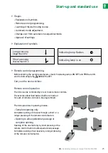
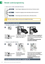
Страница 25: ...r pressing of the remote control button Opening to allow pedestrian passage or complete opening Opening of the one leaf only by short pressing of the remote control button to allow pedestrian passage Complete opening of two leaves by a longer pressing of the remote control button Short pressing shorter than 0 5 s Long pressing longer than 0 5 s Indicating lamp is on Indicating lamp flashes Stages ...

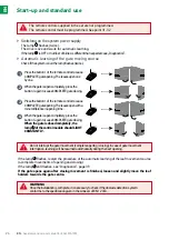
Страница 26: ...mpflashes twice Pressthebutton1oftheremotecontroltocause COMPLETEgateopening Theleavesopenone byone Whenthegateisopencompletely pressthe button1againtocauseCOMPLETEgateclosing Pressthebutton1oftheremotecontroltocause COMPLETEgateopening Theleavesopenwitha minordifferenceinopeningtime Whenthegateisopencompletely pressthe button1againtocauseCOMPLETEgateclosing When the gate is closed completely the ...

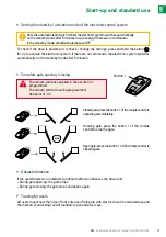
Страница 27: ...gate with electric drive the standard use and the method of unlocking and of mandatory periodical surveys Setting the stand by activation mode of the electronic control system Complete gate opening closing Obstacle detection Training for users Closed gate press the button 1 of the remote control to openthegatecompletely Running gate press the button 1 of the remote control to stop the gate Open ga...

Страница 28: ...enewed pressing of the active button Closing by renewed pressing of the active button Pressandhold thebutton oftheelectronic controlsystemfor2s Thelamp lightsup Puttheremotecontrolon thediscoftheelectronic controlsystem Pressthebutton2oftheremote control LampsRADIOand lightupand thengoout The function of opening to allow pedestrian passage has been activated in this button 1 2 3 28 EN Assembly and...

Страница 29: ...1 4 5 2 3 Pressandholdthe button of theelectroniccontrol systemfor2s Thelamp lightsup Holdthepressedbutton2oftheremotecontroluntil thelamp goesoutandthenitlightsconstantly Releasethebutton2 thelamp flashes pressthebutton1oftheremotecontroltwice Thelamp keepslighting The automatic closing function is ON Puttheremotecontrolon thediscoftheelectronic controlsystem Holdthepressedbutton1oftheremotecontr...

Страница 30: ...trolsystem Pressthebutton 1oftheremote controltwice Thelamp isOFF The automatic closing function is OFF Pressthebutton2oftheremotecontrol Thelamp flashes Holdthepressedbutton1of theremotecontroluntilthe lamp startsflashing Switching off the automatic closing 30 EN Assembly and service manual for EASY WAY202 EN 2s x2 2 Advanced settings ...

Страница 31: ...omfyRTS Anotherequipment ofSomfyRTS Method 3 Anotherequipment ofSomfyRTS Anotherequipment ofSomfyRTS Completeopening Openingtoallow pedestrianpassage oranotherautomatic mechanismofSomfyRTS Method 4 Anotherequipment ofSomfyRTS Innymechanizm automatycznySomfyRTS Innymechanizm automatycznySomfyRTS Completeopening 31 EN Assembly and service manual for EASY WAY202 EN 3 4 1 2 1 2 Remote control with 2 b...

Страница 32: ...lsystemfor2s Thelamp lightsup Putanewremotecontroltobe programmedonthediscofthe electroniccontrolsystem Putanewremote controltobeprogrammed onthediscoftheelectronic controlsystem Shortlypressthebuttontobeprogrammedof theremotecontrol Thelamp RADIO lights upandthengoesoutwhentheremotecontrol buttonisreleased The complete opening mode has been programmed in this button Shortlypressthebuttontobeprogr...

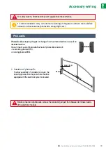
Страница 33: ...Youcanmountasetofphotocells Eachsetofphotocellsconsistsof transmittingphotocell TX receivingphotocell RX Location of photocells To allow assembly of conductors locate the receivingphotocellonthepostwherethedrive equippedwiththeelectronicsystemislocated 2 8m 25 cm max 20 cm 33 EN Assembly and service manual for EASY WAY202 EN Accessory wiring It is recommended to carry out automatic learning of the...

Страница 34: ...nt is finished Operation using the photocells If the photocells are covered during gate closing the gate will stop and start to open again In case of photocell removal After the photocells are removed switch on the drive power supply again and then carry out the procedure Switching off the automatic closing page 30 Orange light operation The orange light flashes when the gate is moving 34 EN Assem...

Страница 35: ...hnical condition Optimum time of charging the battery before use 48 hours Battery life 3 years To ensure optimum battery life disconnect the gate power supply 3 times a year to allow its supplying from the battery during several operation cycles Spare rechargeable battery ON OFF AUTO PROG ON OFF AUTO PROG NO Donotlocatethebatteryconductorabovethepower supplysource 35 EN Assembly and service manual...

Страница 36: ... of 230 V when it is connected to solar energy supply source as this can lead to damage of the electronic drive module Zone lighting operation The zone lighting is activated every time when the drive is started It goes out automatically at expiration of 1 minute and 30 seconds after the movement is finished When the drive is powered by solar energy then the gate can be controlled only by means of ...

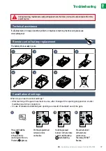
Страница 37: ...htsup Puttheprogrammed remotecontrol onthedisc Holdthepressed button1oftheremote controluntilthelamp startsflashing Pressthebutton1 oftheremote controlonce Thelamp RESET flashes 1 2 3 4 When do you need to cancel settings After learning of the gate movement course after change of the opening stop position or after modification of drive conductors In case of renewed accidental gate opening as a res...

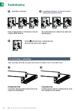
Страница 38: ... in case of an electric fault Thelamp flashestwice see Automaticlearning ofthegatemovementcourse page26 Pressandholdthebutton2oftheremotecontroluntil alllampslightup Locking the drives Installtheactuator Fastentheunlockingelementonthe drivemandreltolockthemandrel Cancellation of settings Cancellation of settings and remote controls control points saved in memory 1 5 7 2 6 38 EN Assembly and servic...

Страница 39: ...vement course see page 26 3 blinks Damaged photocells Check if there is no obstacle between the photocells Check photocell setting Check photocell conductors see page 34 If the photocells were disconnected intentionally carry out the procedure Switching off the automatic closing page 30 4 blinks START control of the electronic module terminals 5 6 is always ON Check accessories connected to START ...

Страница 40: ...Oziemkówka 57A 08 420 Miastków Kościelny Polska Tel 48 25 683 05 55 e mail oziemkowka polargos pl www polargos pl EN ...

Отзывы: