background image


PNI Sensor 


DOC# : PlacePod Installation Guide R01_draft7 

Page 10 of 14 

6  SURFACE MOUNT INSTALLATION PROCEDURE 

This section will outline the steps needed to be performed when physically installing a surface 
mount PlacePod.  


6.1 

PREPARING PARKING SPOT 

1.  Clear any debris in the park space with the deck broom. 
2.  Clean center of parking space(s) using locally available asphalt/concrete cleaner and 

stiff bristle scrub brush. 

3.  If necessary, remove sealer from the pavement surface in the area where the sensor is 

to be placed and repeat the above. 

a.  This is necessary for longer lasting bond. 
b.  Sealant layer can de-laminate from pavement while remaining attached to the 

sensor housing. 

4.  Mark the center of each space using the chalk snap-line. 


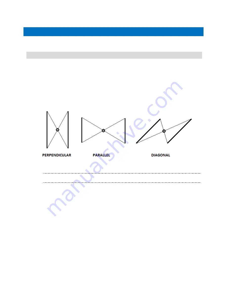
Figure 12: Align PlacePod with center of parking space 


If you intend to screw the PlacePod down to the pavement follow the below steps. 

Note:  To optimize signal strength orient the sensor in the middle of the space such that the 
arrow (inside the half circle next to the “P”) points towards the nearest gateway. 

5.  Place the PlacePod Surface Mount hole pattern, provided at the end of this document, 

at the center of the spot and mark each screw hole location. Alternatively you can use 
the PlacePod housing itself to mark the holes through the housing. ONLY mark the 
holes through the housing, do NOT drill the holes through the housing. 

6.  Use the Hammer Drill to drill the screw holes. Do NOT drill the holes through the 

PlacePod sensor as the vibration and shock from the drill can damage the components 
inside the sensor. 


Содержание 13ZD

Страница 1: ...onic de PART OF LAGERCRANTZ GROUP ELECTRONICS UNITRONIC GmbH Mündelheimer Weg 9 40472 Düsseldorf Telefon 0211 95 110 Telefax 0211 95 11 111 info unitronic de PART OF LAGERCRANTZ GROUP PLACEPOD SMART PARKING SENSOR INSTALLATION GUIDE Instructions for physical installation of a PlacePod Smart Parking Sensor ...

Страница 2: ...MOUNT SPECIFIC EQUIPMENT 5 4 INSTALLATION ON GRADED SURFACES 6 5 IN GROUND INSTALLATION PROCEDURE 7 5 1 PREPARING THE PARKING SPACE 7 5 2 DRILL THE CORE 7 5 3 REMOVE THE CORE 7 5 4 PREPARE THE HOLE FOR THE PLACEPOD 8 5 5 INSERT THE PLACEPOD INTO THE HOLE 8 5 6 SEAL THE HOLE 9 6 SURFACE MOUNT INSTALLATION PROCEDURE 10 6 1 PREPARING PARKING SPOT 10 6 2 PREPARING PLACEPOD FOR ADHESIVE 11 6 3 INSTALL ...

Страница 3: ...accurate magnetic sensing system for vehicle detection with the combination of PNI s high performance magnetic sensor and vehicle detection algorithms that accurately detect the presence or absence of a car in a parking space Includes a built in LoRa radio that communicates to a gateway or base station with complete LPWAN compatibility Sensors and algorithms are finely tuned for ultra low power co...

Страница 4: ... onto your PNI Cloud account or ensure it is provisioned onto the LoRa Network you intend to use 2 2 PREPARING THE PARKING SPACE 1 Clear any debris in the park space with a deck broom 2 Using a tape measure or chalk snap line locate the center of the parking space 3 Mark the center of each space using the chalk snap line Figure 3 Align PlacePod with center of parking space 2 3 PARKING LOT MAP RECO...

Страница 5: ...draft7 Page 4 of 14 Figure 5 Sample Parking Map with PlacePod Serial Numbers 3 Knowing the location of where each sensor is installed is useful for individual parking space monitoring as well as trouble shooting sensor performance and communication ...

Страница 6: ...per 2 part kit using minimum application 3 2 SURFACE MOUNT SPECIFIC EQUIPMENT Coarse Sand Paper Adhesive and Applicator o At the time of writing PNI recommends Superior Industries 303 Bumper Mount which can be ordered directly from the manufacturer o https www superior industries com _303_bumper_mount_product_278 html o Approximately 6 sensors per 2 part kit using minimum application Concrete Seal...

Страница 7: ...IME OF THE PRODUCT IMPROPER INSTALLATION MAY RESULT IN SHORTENED PRODUCT LIFETIME 1 Pavement angle must be taken into account when drilling the core The depths specified in the following pages are based on a level surface Depth measurements must be made from the lowest point on the graded surface as shown in the illustration below particularly if the core drill rig places the core bit perpendicula...

Страница 8: ... is preferred Note If you do not drill through to the bedding layer you will need an extra step to remove the core This usually involves an impact device such as a jack hammer or air chisel 3 Optional Flush the drilling surface with water to lubricate the drill and dampen dust Figure 6 Drill the hole for the PlacePod 5 3 REMOVE THE CORE Remove the core after drilling is done 1 If drilling down to ...

Страница 9: ...ely affecting epoxy performance and adhesion 3 Add epoxy to level the surface to 1 5 inches depth from pavement surface Allow epoxy to harden Figure 9 Bottom Layer of epoxy 5 5 INSERT THE PLACEPOD INTO THE HOLE 1 If mapping of the sensor location is being performed record the sensor Serial Number 2 Add a second layer of epoxy approx 1 4 inch thick 3 Insert the sensor into the hole so that it is se...

Страница 10: ...ous step has cured remove the weight and fill the remainder of the hole with the epoxy until it is flush with the pavement surface To reduce formation of bubbles fill in any gaps between the sensor and the wall of the hole before covering the top of the sensor 2 Make sure the epoxy completely covers the top of the sensor and is flush or slightly below flush with the pavement surface WARNING The ep...

Страница 11: ...ing 4 Mark the center of each space using the chalk snap line Figure 12 Align PlacePod with center of parking space If you intend to screw the PlacePod down to the pavement follow the below steps Note To optimize signal strength orient the sensor in the middle of the space such that the arrow inside the half circle next to the P points towards the nearest gateway 5 Place the PlacePod Surface Mount...

Страница 12: ...the outer and inner rings of the PlacePod 3 If desired adhesive can be applied to the ribs and to the sensor lower housing black areas NOT covered by the label Figure 14 Apply adhesive to outer ring and any additional ribs of the gray housing 4 To optimize signal strength orient the sensor in the middle of the space such that the arrow points towards the nearest gateway 5 Place the sensor on the g...

Страница 13: ...the center of the parking space with the pre drilled screw holes 2 Screw the PlacePod down with the Masonry Screws hand tighten Do not over tighten the screws as this can damage the PlacePod housing Figure 25 Drill Dimensions Drilling dimensions Drill bit size determined by screw manufacturer ...

Страница 14: ...he PlacePod taking it out of shipping mode such that it begins sending RF messages 2 Calibrate the PlacePod sensor for the empty parking space This is important and required of each sensor If calibration is not properly performed the PlacePod will not detect vehicles accurately Instructions for these additional steps and other PlacePod support documentation can be found under your PNI Cloud accoun...

Страница 15: ...r identification marks have been defaced damaged or removed This warranty does not cover wear and tear due to normal use or damage to the Product as the result of improper installation usage neglect of care alteration accident or unauthorized repair THE ABOVE WARRANTY IS IN LIEU OF ANY OTHER WARRANTY WHETHER EXPRESS IMPLIED OR STATUTORY INCLUDING BUT NOT LIMITED TO ANY WARRANTY OF MERCHANTABILITY ...

Отзывы: