background image

12

When an AC power adapter is used with a printer that has been verifi ed to be operational, although the printer type may differ 
from that of the connection diagrams (e.g., a built-in type, or assembled type), the connections should be performed based on 
the same main points. (In accordance with the printer specifi cations)

Step 

1


Connecting the main unit 

and printer

Step 

2


Mounting the AC adapter box 

to the printer table

Step 

3


Wiring the cables in the 

cable cover(s)

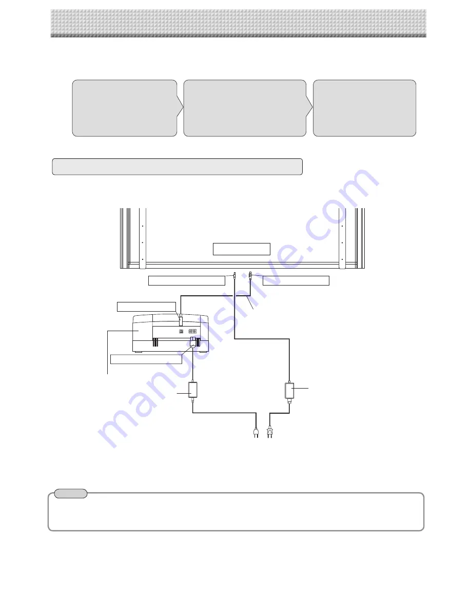
 Step 1: Connecting the main unit and printer

* Appearance of printer is for illustration purposes.

Back surface

To DC INPUT connector 

To Printer connector 

To USB connector 

Printer

USB cable (supplied)

To DC input connector 

AC power adapter (supplied)

Printer AC power adapter
 supplied with the printer

Note

7. CONNECTION TO THE SET

After connecting the main unit and printer, place the AC power adapters in the AC adapter box.

• 

Flow of connection operations

Connect as shown on the diagram below. Do not yet connect the AC power plugs of the AC power 
adapters to wall power outlets.

Содержание C-12 Series

Страница 1: ...e the set yourself To the Dealer or Installation Tradesman In the interest of the safety of the customer please perform installation work paying due attention to the strength of the installation locat...

Страница 2: ...screws for the wall mounting portion Use of screws other than M6 or equivalent can result in the main unit falling and causing injury Please mount to a post in the wall or a sturdy wall stud When the...

Страница 3: ...rd type 1 Wide type 2 AC power adapter with power code 1 HEC AP065 24V Markers 4 One each of black red blue and green Eraser 1 USB cable 1 Documentation Instruction manual 1 CD ROM 1 Quick Guide 1 Ass...

Страница 4: ...eg Diagrams of printers that appear in this manual are representative illustrations The illustration will differ from the actual printer Check the owner s manual of your printer for information about...

Страница 5: ...Mount the printer table to the main unit See Page 10 for information about the assembly and installation of the printer table Installation of the printer table is not required when the main unit is u...

Страница 6: ...d Mount the stay to the printer table using two M3 screws Check again that the grooves in the stand s hooks are se curely inserted in the mounting holes in the support fittings 8 Lock the main unit an...

Страница 7: ...wall support fitting to the post or stud When the building does not have posts please use the stand Separate optional items are available when the standard wall mounting is not possible or when insta...

Страница 8: ...the cushions adhesive surfaces Stick the cushions 2 on the back of the bracket See page 10 for instructions on assembling and mounting the printer table When mounting the printer table after installi...

Страница 9: ...ng the main unit to a wall or wall support fitting The anchoring method will differ depending on the wall mounting method Installing on a Concrete Wall Anchor nut etc M6 screw Mounting to a Post M6 wo...

Страница 10: ...ews in the order of Steps to Right bracket Left bracket M4x8 screws Front screw hole Front screw hole When mounting the printer table after installing the main unit on a wall Use four M4 8 screws to t...

Страница 11: ...rinter guide M3 6 screws Peel off the backing paper from the Velcro and attach the Velcro to the bottom of the printer Do not attach the Velcro to a sunken surface of the printer or it will not stick...

Страница 12: ...Step 3 Wiring the cables in the cable cover s Step 1 Connecting the main unit and printer Appearance of printer is for illustration purposes Back surface To DC INPUT connector To Printer connector To...

Страница 13: ...the main unit and printer in the AC adapter box Catch the hooks on the ends of the AC adapter box onto the bottom of the left and right brackets the L shaped part To catch the hooks insert the AC adap...

Страница 14: ...or a 200V power cord 1 Attach the cable cover s according to the type you have purchased Peel off the backing paper from the cable cover and attach the cable cover firmly to the bracket When the main...

Страница 15: ...he stand AC power adapter s power plug Wall power outlet Cable cover specifically for the main unit Cable cover specifically for the main unit Example of connection cable wiring Standard type stand in...

Страница 16: ...16 Back surface AC power adapter s power plug Wall power outlet Cable cover specifically for the main unit Standard type wall installation 7 CONNECTION TO THE SET...

Страница 17: ...Check that the number of copies indicated in the display window of the main unit is 01 and then press the Print button On the C 12 Series the display will indicate PC or OP Check this indication and p...

Страница 18: ...stay in its original position See 7 on page 5 for mounting instructions 5 Attach the locking screws to the 2 locations left and right and tighten to the rear frames 6 Return to original by following t...

Страница 19: ......

Страница 20: ...23 4604 08B 2008 PLUS Corporation...

Отзывы: