Power and Control
46
Plockmatic PowerSquare™ 160 - Service Training Workbook
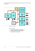
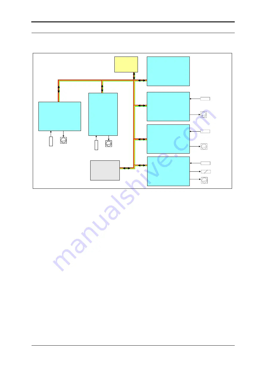
Figure 24. The CAN Bus
Refer to the following:
• 7.2.1 Bookmaker Module Electrical Layout Diagram
• 7.2.2 Staple - Clinch Module Electrical Layout Diagram
• 7.2.3 Transport Module Electrical Layout Diagram
• 7.2.5 Bridge Electrical Layout Diagram
Inverter
GUI
Rotate
900-308
PCB
M
Stepper
Motor
Sensors
CAN Bus
M
Stepper
Motors
Sensors
Uplift
900-310
PCB
Staple
900-308
PCB
Transport
900-303
PCB
Bookmaker
900-306
PCB
Power & Comms
Distribution
900-316 PCB
M
M
M
Stepper
Motors
Stepper
Motors
Stepper
Motors
Sensors
Sensors
Sensors
Solenoid
Node 32
Node 36
Node 05
Node 38
Node 68
Node 64
Содержание Morgana PowerSquare 160
Страница 72: ...Glossary of booklet making terms 68 Plockmatic PowerSquare 160 Service Training Workbook...
Страница 73: ......
Страница 74: ......
Страница 75: ......

