25 November 2011
CF-3-10
3.2.6 DRIVE MOTOR M16 ASSEMBLY
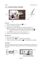
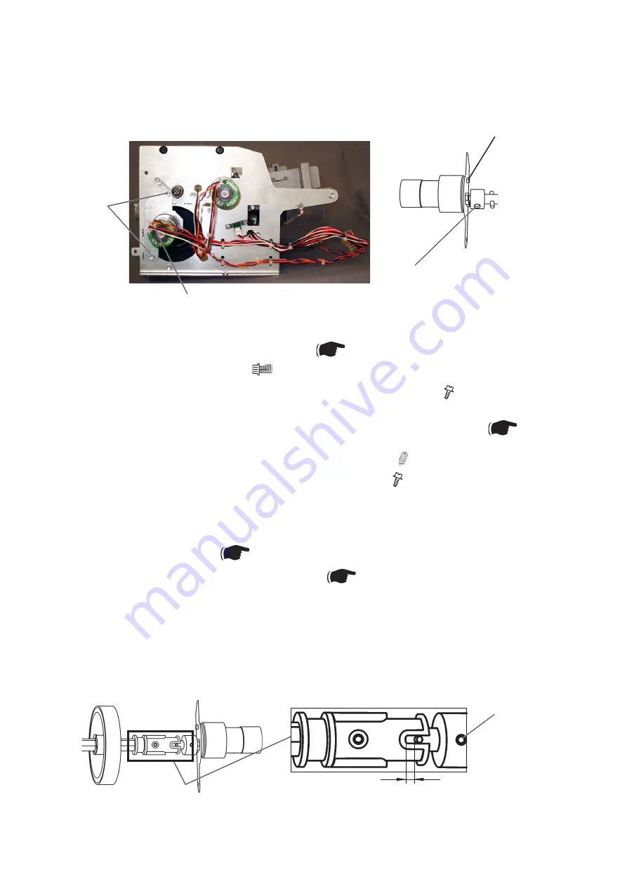
[A]
0.4 ± 0.3 mm play between
the coupling and the clutch
Removal
1. Remove complete Cover Feeder unit (
1.1.1).
2. Disconnect Connector [A] (
x1).
3. Remove Drive motor M16 assembly by removing screws [B] ( x2).
NOTE:
Be careful when removing the Drive motor M16 assembly, so that the
Drive Shaft Assembly will not damage the LED sensor CF-Q30 (
3.2.9).
4. Loosen the allen screw [C] to Drive clutch assembly ( x1).
5. Remove the motor bracket by removing screws [D] ( x3).
[B]
[C]
[D]
Replacement
1. Reverse the removal procedure.
2. Enter Service mode (
5.1.1 in BK5030 Service Manual).
3. Perform Cover Feeder motor calibration (
5.5 in BK5030 Service Manual).
Adjustment
Adjust the Drive clutch assembly, so that there is play between the coupling on the
Drive shaft and the Clutch. The play should be 0.4 ± 0.3 mm. Adjust by loosening
screw [C].
AREA F
[C]
Содержание CF5030
Страница 1: ...25 November 2011 Subject to change COVER FEEDER CF5030 SERVICE MANUAL...
Страница 2: ...Page intentionally blank...
Страница 4: ...Page intentionally blank...
Страница 6: ...Page intentionally blank...
Страница 8: ...Page intentionally blank...
Страница 12: ...Page intentionally blank...
Страница 42: ...Page intentionally blank...
Страница 44: ...25 November 2011 CF 6 2 ELECTRICAL COMPONENT LIST 6 1 1 REAR VIEW CF M15 CF M16 CF Q33...
Страница 46: ...Page intentionally blank...
Страница 48: ...Page intentionally blank...
Страница 50: ...Page intentionally blank...
Страница 51: ...CF Wir 1 25 November 2011 Wiring WIRING Cover Feeder Included in wiring diagram to BK5030 See separate document...
Страница 52: ...Page intentionally blank...


