
SPECIFICATIONS AND FEATURES
1.
Key Code Range
5 digit code:
00000-99999
4 digit code:
0000-9999
Memory Capacity:
10,000 (4 digit), 100,000 (5 digit) codes
2.
RFID Card Reader
Card Code Capacity:
2000 Cards
3.
Keypad
Keys:
0-9, "*" start over, "#" command code
Key entry timeout: 15 sec (uncompleted key code will be ignored in 15
sec idle period.)
4.
RF Remote Control
Working with Platinum RF receiver to provide >50ft remote control.
5.
Hold Open Code
Resettable 5 digit code to turn on/off hold open operation.
6.
Request to Exit Input
A contact input for codeless open activation..
7.
Adjustable Control Output Strike Duration
0-99s output relay and RF control strike duration.
8.
Slave Mode
It can be set to slave mode to work with master. All codes entered will
be send back to master to verify, Master will send gate open command
upon valid key code. 99 slave ID’s can be set with on board rotary
switch.
9.
Backlit Key
Back light of the keys will be turn on automatically when the
environmental light is dimmed.
10.
Control Output
a. NO/NC relay output with 10Amp @ 120VAC or 8A @ 30VDC.
b. Solid state output with 0.5A sink current.
11.
Battery Backup
Internal rechargeable battery provides >24 hours power backup.
12.
Solar Panel Ready
A 12V/20W solar panel can be connected to power the unit and charge
the battery for AC power free operation.
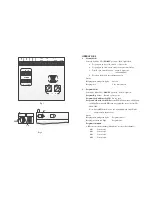
INSTALLATION
1.
Wring
See Fig.1.
a.
Connect 9V/2A AC/DC adaptor to “AC/DC” terminals.
b.
Connect solar panel to “SOL” terminals.
c.
Connect the internal battery to either “BAT1” or “BAT2” terminal.
d.
Connect NC/COM/NO to external device under control.
e.
Connect “EXIT” to external strike open switch.
f.
Connect RS485 cable from master to either of the RS485 terminals.
2.
Set the Mode DIP Switch
a.
Set 4 or 5 digit length operation by “DIG” side DIP SW.
b.
Set master/slave by side “M/S” side DIP SW “M” or “S”.
3.
Set the Slave Device ID
Set slave device ID by the 2 rotary decimal SW. set range 00-99.
4.
Indicator and Mode Switch Locations
See Fig.2.


