background image


  LoRa Node Controller 

LN501 and LN1152


- 21 - 

4.2  LoRaWAN setting 

  LoRaWAN setting is used for configuring the transmission parameters in LoRaWAN ® network. 


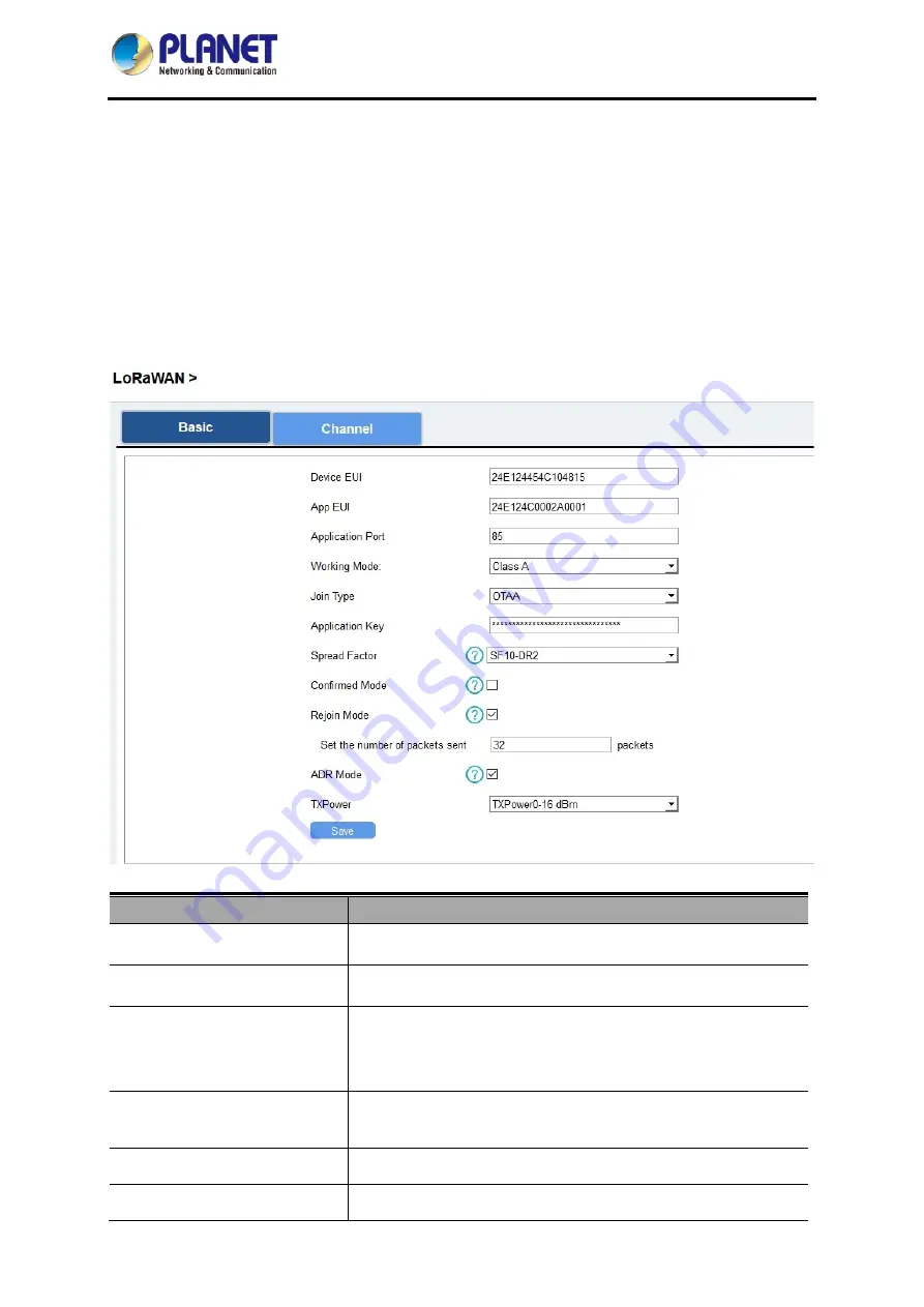
Basic LoRaWAN Settings: 

Go to “

LoRaWAN

 -> 

Basic

” of ToolBox software to configure join type, App EUI, App Key and other 

information. You can also keep all settings by default. 


Object 

Description 

Device EUI 

Unique ID of the device which can also be found on the label. 

App EUI 

Default App EUI is 24E124C0002A0001. 

Application Port 

The port is used for sending and receiving data; default port is 

85. 

Note: RS232 data will be transmitted via another port. 

Working Mode 

LN501: Class A and Class C are available; 

LN1152: Class C. 

Join Type 

OTAA and ABP mode are available 

Application Key 

Appkey for OTAA mode; default is 

Содержание LN1152

Страница 1: ...LoRa Node Controller LN501 and LN1152 1 LoRa Node Controller LN501 and LN1152 ...

Страница 2: ...ve occurred Information in this User s Manual is subject to change without notice and does not represent a commitment on the part of PLANET PLANET assumes no responsibility for any inaccuracies that may be contained in this User s Manual PLANET makes no commitment to update or keep current the information in this User s Manual and reserves the right to make improvements and or changes to this User...

Страница 3: ...ealth as a result of the presence of hazardous substances in electrical and electronic equipment end users of electrical and electronic equipment should understand the meaning of the crossed out wheeled bin symbol Do not dispose of WEEE as unsorted municipal waste and have to collect such WEEE separately Trademarks The PLANET logo is a trademark of PLANET Technology This documentation may refer to...

Страница 4: ... Physical Descriptions 11 2 2 Hardware Installation 14 Chapter 3 Preparation 18 3 1 Requirements 18 3 2 Managing LoRa Node 18 Chapter 4 Operations Management 19 4 1 Managing LoRa Node 19 4 2 LoRaWAN setting 21 4 3 Interface setting 24 4 3 1 RS485 Settings 25 4 3 2 RS232 Settings 28 4 3 3 GPIO Settings 29 4 3 4 AI Settings 31 4 4 Maintenance 33 4 4 1 Upgrade 33 4 4 2 Backup 33 4 4 3 Reset to Factor...

Страница 5: ...n Thank you for purchasing PLANET LoRa Node Controller LN series The descriptions of these models are as follows LN501 Outdoor IP67 LoRa Node Controller with Solar Panel LN1152 Indoor IP30 LoRa Node Controller LoRa Node mentioned in the manual refers to the above models ...

Страница 6: ...Quick Installation Guide x 1 Data Cables x 2 Mounting Bracket x 1 Wall Mounting Kits x 1 Hose Clamps x 2 2550 mAh Battery x 2 LoRa Node Controller x 1 Quick Installation Guide x 1 LoRa Antenna x 1 12 Pin Terminal Block x 1 Wall Mounting Screws x 2 Power Adapter x 1 If any of the above items are missing please contact your dealer immediately ...

Страница 7: ...trigger multiple conditions and actions without a network With its industrial design and IP30 metal case the LN1152 is widely used in indoor applications like smart industries building automation etc LoRaWAN based Controller with Rich Industrial Interfaces The LoRa Node Controller with built in multiple industrial interfaces connects to all types of sensors meters and other appliances It also brid...

Страница 8: ... and built in battery optional Quick wireless configuration via NFC Compliant with standard LoRaWAN gateways and network servers LN1152 Easy to connect with multiple wired sensors through GPIO RS232 RS485 interfaces Ultra wide distance transmission up to 10km with line of sight Triggers multiple conditions and actions Embedded watchdog for work stability Industrial metal case design with wide oper...

Страница 9: ... Ports 1 RS232 or RS485 Switchable Baud Rate 300 115200 bps Protocol Transparent RS232 Modbus RTU RS485 Analog Input Ports 2 Analog input Resolution 12 bit Input Range 4 20mA or 0 10V Switchable Power Output Ports 2 3 3 V 2 5 9 12 V Switchable Operation Power On Off NFC power button Internal Configuration PC software via USB Type C or NFC Physical Characteristics Operating Temperature 20 C to 60 C...

Страница 10: ...24VDC pulse counter support Digital Output SPDT Relay Contact Rating 3A DC Max 30 V or AC Max 250 V Serial Port Ports RS232 RS485 Baud Rate 4800 115200bps RS232 1200 115200 bps RS485 Protocol Transparent RS232 Modbus RTU RS485 Others Configuration Port 1 Micro USB LED Indicators 1 System 1 ACT Built in Watchdog Timer Physical Characteristics Power Connector 3 5mm terminal block Power Supply 5 24 V...

Страница 11: ...1 on 2 off 3 off default 9V 1 off 2 on 3 off 5V 1 off 2 off 3 on Analog Input Disable 1 off 2 off 3 off 4 20mA ADC 1 off 2 on 3 on default 0 10V ADC 1 on 2 off 3 off RS485 Disable 1 off 2 off 3 off default Add 120 Ω resistor between A and B 1 on 2 off 3 off Add 1k Ω pull up resistor on A 1 off 2 on 3 off Add 1k Ω pull down resistor on B 1 off 2 off 3 on ...

Страница 12: ...button for more than 10s Blinks Check On Off Status Quickly press the power button Light On Device is on Light Off Device is off Data Interface Data Interface 1 Pin Description 1 5V 9V 12V OUT Switchable 2 3 3V OUT 3 GND 4 Analog Input 1 5 Analog Input 2 6 5 24V DC IN Data Interface 2 Pin Description 1 5V 9V 12V OUT Switchable 2 3 3V OUT 3 GND 4 GPIO1 5 GPIO2 6 RS232 RS485 Switchable 7 8 Reserved ...

Страница 13: ...UT_COM DO 11 OUT_NC 12 OUT_NO LED Definition LED Indication Status Description System System Status Static System Start up On for 500 ms off for 500 ms The system is running properly On for 200 ms off for 200 ms The system is not connected to server ACT Network Status Off Failed to access the network On for 500 ms off for 500 ms Accessed the network successfully ...

Страница 14: ... 2 2 2 Wall Mounting LN501 Make sure you have a wall mounting bracket bracket mounting screws wall plugs wall mounting screws and other required tools Step 1 Mark the four holes on the wall you prefer to place the device and drill the marked four holes for the wall plugs anchors Then place the mounting bracket over the holes with the wall plugs inside and tighten it with the screws Step 2 Place th...

Страница 15: ...sired position on the wall and use a marker pen to mark two mounting holes on the wall Step 2 Drill the two holes marked previously on the wall by using your drill with a 6 mm drill bit Step 3 Mount the device to the wall by tightly screwing the wall mounting screws M3 20 into the device mounting holes ...

Страница 16: ...LoRa Node Controller LN501 and LN1152 16 2 2 3 Application Wiring Digital Input Digital Output Analog Input RS232 RS485 ...

Страница 17: ... LN1152 17 LN1152 series supports 5 24 V DC power supply You can use other supplies or power adapter to power on the device For industrial applications it s suggested not to release the metal case and use an independent power supply ...

Страница 18: ... 2008 Type C USB cable for LN501 Micro USB cable for LN1152 3 2 Managing LoRa Node 1 Download ToolBox software from Planet web site 2 https www planet com tw en support downloads method keyword keyword LN501 view 6 list 3 Power on the LoRa Node device and then connect it to computer via micro USB port 4 Open the ToolBox and select Type and then General and then click password to log in ToolBox Def...

Страница 19: ...ging LoRa Node 5 Download ToolBox software from Planet web site 6 https www planet com tw en support downloads method keyword keyword LN501 view 6 list 7 Power on the LoRa Node device and then connect it to computer via micro USB port 8 Open the ToolBox and select Type and then General and then click password to log in ToolBox Default password 123456 ...

Страница 20: ...LoRa Node Controller LN501 and LN1152 20 9 After logging in the ToolBox you can click Power On or Power Off to turn on off device and change other settings ...

Страница 21: ... You can also keep all settings by default Object Description Device EUI Unique ID of the device which can also be found on the label App EUI Default App EUI is 24E124C0002A0001 Application Port The port is used for sending and receiving data default port is 85 Note RS232 data will be transmitted via another port Working Mode LN501 Class A and Class C are available LN1152 Class C Join Type OTAA an...

Страница 22: ...st Rejoin Mode Reporting interval 30 mins the device will send specific mounts of LoRaMAC packets to check connection status every 30 mins If no reply after specific packets the device will re join Reporting interval 30 mins the device will send specific mounts of LoRaMAC packets every to check connection status every reporting interval If no reply after specific packets the device will re join No...

Страница 23: ... of the channel that you want to enable in the input box making them separate by commas Examples 1 40 Enabling Channel 1 and Channel 40 1 40 Enabling Channel 1 to Channel 40 1 40 60 Enabling Channel 1 to Channel 40 and Channel 60 All Enabling all channels Null Indicates that all channels are disabled ...

Страница 24: ...terval Object Description Reporting Interval Reporting interval of transmitting data to network server Default 20 mins Range 1 1080 mins Note RS232 transmission will not follow the reporting interval Device Returning Power Supply State If the device loses power and returns to power supply the device will be on or off according to this parameter Interface 1 2 3V3 Output Enable 3 3V power output Aft...

Страница 25: ...e the same as RS485 terminal devices Object Description Interface 2 Pin 1 5V 9V 12V Enable 5V 9V 12V power output of interface 2 to supply power to RS485 terminal devices It s 12V by default and you can change DIP switches to change voltage Power Output Time Before Collect LN501 will power the RS485 terminal devices for a period of time before collecting data for terminal device initialization Bau...

Страница 26: ...and send Modbus reply originally back to network server Port Select from 2 84 86 223 When you use power output to power RS485 Modbus slave devices it only supplies power when reporting interval is coming It s suggested to power slave devices with external power during the PoC test 3 Click to add Modbus channels and then save configurations Object Description Channel ID Select the channel ID you wa...

Страница 27: ...and to terminal device regularly 01 03 00 00 00 01 84 0A 4 For ToolBox software click Fetch to check if LN501 can read correct data from terminal devices You can also click Fetch on the top of list to fetch all channel data Please do not click Fetch frequently since response time to reply is different for every terminal device ...

Страница 28: ...ttings Serial port settings should be the same as RS232 terminal devices Object Description Interface 2 Pin 1 5V 9V 12V Enable 5V 9V 12V power output of interface 2 to supply power to RS232 terminal devices continuously Note Power output is 12V by default and you can change DIP switches to change voltage Baud Rate 1200 2400 4800 9600 19200 38400 57600 115200 are available Data Bit 8 bit is availab...

Страница 29: ...evices to GPIO ports on interface 2 2 Go to General GPIO of ToolBox software to enable GPIO port 3 Select GPIO type according to your requirements Digital Input detect high or low status of devices Digital Output send voltage signal to trigger devices Counter pulse counter ...

Страница 30: ... selected falling edge will be triggered if pull down is selected rising edge will be triggered After selection click Fetch to check current status of digital input Digital Output Click Switch to check if LN501 can trigger devices by digital output or click Fetch to check the current status of digital output ...

Страница 31: ...eep the counted values when the device powers off Start Stop Make the device start stop counting Note LN501 will send non changeable counting values if you do not click Start Refresh Refresh to get latest counter values Clear Count the value from 0 4 3 4 AI Settings 1 Connect analog device to analog input ports on interface 1 If you need LN501 to power the analog device connect the power cable of ...

Страница 32: ...1 Pin 1 5V 9V 12V and configure Power Output Time Before Collect LN501 will power the analog devices for a period of time before collecting data When you use power output to power analog devices it only supplies power when reporting interval is coming It s suggested to power slave devices with external power during the PoC test 5 Click Fetch to check if LN501 can read correct data from analog devi...

Страница 33: ...e device and upgrade 4 4 2 Backup LN501 devices support configuration backup for easy and quick device configuration in bulk Backup is allowed only for devices with the same model and LoRa frequency band Please select one of following methods to back up device 1 Go to Maintenance Backup and Reset click Export to save current configuration as backup file 2 Click Browse to select backup file and the...

Страница 34: ...1152 34 4 4 3 Reset to Factory Default Please select one of following methods to reset device Hardware Open the case of LN501 and hold on power button for more than 10s ToolBox Software Go to Maintenance Backup and Reset to click Reset ...

Отзывы: