ICA-HM127
ICA-HM127
Quick Guide
Quick Guide
2011-AB5620-000
PLANET Technology Corporation
Tel: 886-2-2219-9518
Fax: 886-2-2219-9528
Email: [email protected]
www.planet.com.tw
11F., No.96, Minquan Rd., Xindian Dist., New Taipei City 231, Taiwan (R.O.C.)
PLANET reserves the right to change specifications without prior notice. All brand names and trademarks are property of
their respective owners. Copyright © 2011 PLANET Technology Corp. All rights reserved.
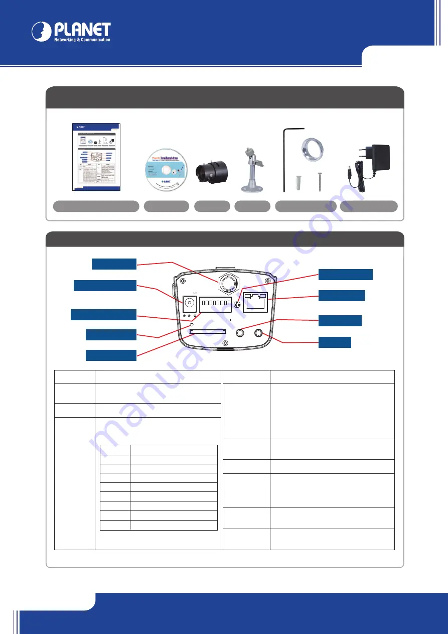
VERIFY THE CONTENTS INSIDE PACKAGE BOX
The package should contain the items plus ICA-HM127. If any item is missing or damaged, please contact the seller immediately.
Quick Installation Guide
Step 2a. Connecting Network
Step 3. Computer Network Setup
Set your computer’s IP address to 192.168.0.x, where x is a number between 1 to 253
(except 20 where is being used for the camera by default). If you don’t know how to do
this, please ask your network administrator.
In the ICA-HM127 can be configured without external power, if connecting to an IEEE 802.3af powered Ethernet switch.
Fasten the Lens with IP Camera
NOTE :
Use only the power adapter shipped with the unit to ensure correct functionality
Use web browser (Internet Explorer 6.0 or above) to connect to
192.168.0.20
(type this
address in the address bar of web browser).
You’ll be prompted to input user name and password:
admin
/
admin
.
Further Configuration
For detail configuration, please check user’s manual on the bundled CD.
Step 4. Login Prompt
Power Adapter
Accessories
Lens
Stand
ICA-HM127
Ethernet Switch
User PC
(192.168.0.X)
Step 1. Connecting Lens
CD-ROM
Camera Rear Panel
Step 2b. Connecting Power via PoE interface and Network
ICA-HM127
Ethernet PoE Switch
User PC
(192.168.0.X)
x 3
x 3
Description
Output video signal, connect to external video
devices
Connect to DC power adapter output
Connector Digital input / output dry contacts.
Connects to external peripherals by wire. See next
page for pin definitions.
Item
Description
D+
RS485 signal positive (+)
D-
RS485 signal negative (-)
GND
Signal ground
DO
Digital Output #1
DI1
Digital Input #1
DI2
Digital Input #2
AC24V-
AC 24V power input negative (-)
AC24V+
AC 24V power input positive (+)
WARNING: DO NOT CONNECT POWERED
CABLE!
Description
When the IP camera is not functioning properly,
you can use a pen or similar object to press this
reset button to reset the IP camera. You can also
press and hold this button for more than 5 seconds
to clear all settings of IP camera, include adminis-
trator password, then the IP camera will download
default setting automatically.
Inserts SD card for video recording.
Maximum 32GB of SD-HD card supported.
Adjust the DC lens driving ability
Connect to your local area network by Ethernet
cable.
Left LED: Power indicator
Right LED: Data transfer
Connects to external audio amplifier to output
voice. Use 3.5mm audio cable.
Connects to external microphone to input audio
signal to IP camera. Use 3.5mm audio cable.
Item
1. VIDEO OUT
2. DC 12V*
3. DI/DO
Connector
Item
4. RESET
5. SD
6. DC lens drive
7. ETHERNET
8. AUDIO OUT
9. MIC IN
NOTE :
For "C-mount lens", the adapter must installed. For "CS-mount " the lens can use directly.
*
Note :
ICA-HM127 can be powered either by 12VDC or IEEE 802.3af Power over Ethernet.
6. DC Lens Drive
7. LAN Socket
9. MIC IN
8. Audio Out
1. Video Out
3. DI / DO Connector
4. Reset Button
5. SD Card Slot
2. Power Connector
DC 12V
VIDEO OUT
ETHERNET
RESET
SD
AUDIO OUT
MIC IN
- D +
- D -
- GND
- DO
- D
I1
- D
I2
- AC24V-
- AC24V+
RS485