background image


3

Interface for Arm Applications   

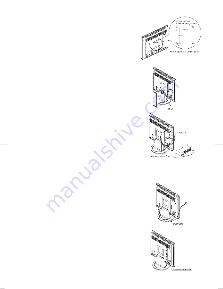
Before installing to mounting device, please refer to Fig.1-2. 
The rear of this LCD display has four integrated 4 mm, 0.7 pitches 
threaded nuts, as well as four 5 mm access holes in the plastic covering 
as illustrated in Figure 1-3. These specifications meet the 

VESA Flat 

Panel Monitor Physical Mounting Interface Standard

 (paragraphs 

2.1 and 2.1.3, version 1, dated 13 November 1997). 

Note :Please using Ø 4mm x 8mm (L) screw for this application.


Figure 1-3


Cable Installation


Please follow these instructions to install the cables. 

1. 

Remove the back panel 

n

 from the rear of the monitor.(See Fig. 

1-4) 

2. 

Place the signal cable, the AC power cable into their correct 
Socket.


Figure 1-4


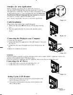
Connecting the Display to your Computer


1. 

Power off your computer.   

2. 

Connect one end of the signal cable to the LCD Monitor’s VGA port 
(See Fig 1-5)   

3. 

Connect the other end of the signal cable to the VGA port on your 
PC. 

4. 

Make sure connection are secure

.


Figure 1-5 

Attention


This device must be connected to an off-the-shelf video cable in order to comply with FCC regulations. A ferrite-core 
interface cable is included in the LCD Monitor package.   
This device will not be in compliance with FCC regulations when a non-ferrite-core video cable is used.   

Connecting the AC Power 


1. 

Connect the power cord to the AC socket.(See Fig. 1-6)   

2. 

Connect the power cord to an AC power source.


Figure 1-6


Setting Up the LCD Monitor 

1. 

Turn on the LCD monitor’s hard power switch, located on the 
back of the monitor (See Fig. 1-7) 

2. 

Turn on the LCD Monitor's soft power switch, located on the 
bezel of the monitor.


 Figure 1-7


Содержание PE190

Страница 1: ......

Страница 2: ...imits are designed to provide reasonable protection against harmful interference in a residential installation This equipment generates uses and can radiate radio frequency energy and if not installed and used in accordance with the instruction may cause harmful interference to radio communications However there is no guarantee that interference will not occur in a particular installation If this ...

Страница 3: ... required to connect this device to a power outlet For a nominal current up to 6A and a device weight above 3 kg a line not lighter than H05VV F 3G 0 75 mm2 must be used Chapter 1 Installation Unpacking Before unpacking the LCD Monitor prepare a suitable workspace for your Monitor and computer You need a stable and clean surface near a wall power outlet Make sure that LCD Monitor has enough space ...

Страница 4: ...1 4 Connecting the Display to your Computer 1 Power off your computer 2 Connect one end of the signal cable to the LCD Monitor s VGA port See Fig 1 5 3 Connect the other end of the signal cable to the VGA port on your PC 4 Make sure connection are secure Figure 1 5 Attention This device must be connected to an off the shelf video cable in order to comply with FCC regulations A ferrite core interfa...

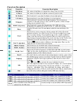
Страница 5: ...ion Select Buttons Press either left or right control button for OSD On Screen Display menu selection 4 Adjustment Control Buttons Press the left button to decrease the OSD setting and press the right button to increase the OSD setting Adjusting the Monitor s Display The monitor has four function control buttons to select among functions shown on OSD menu designed for easy user viewing environment...

Страница 6: ...ase see the diagram below for function and description OSD H Position This function moves the OSD menu window horizontally OSD V Position This function moves the OSD menu window vertically Graph Text Because the H and V Frequencies of both 640 x 400 70Hz and 720 x 400 70Hz are the same this function let s you manually select either 640 x 400 graphics mode or 720 x 400 text mode Recall The recall f...

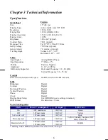
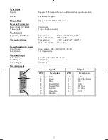
Страница 7: ... 75 Ohm 2 Positive Negative 0 0 7 0 05 Vp Horizontal Frequency 24 80 KHz Vertical Frequency 56 75 Hz Control Power switch hard and soft types On Off switch with LED indicator OSD Brightness Contrast Horizontal Position Vertical Position Phase Clock Display Mode Setup OSD Format Digital Digital Digital Digital Digital Digital Use EEPROM to save settings in memory 20 characters x 9 rows Power Manage...

Страница 8: ...ive Humidity 20 to 80 Storage Condition Temperature 20 C to 60 C 4 F to140 F Relative Humidity 5 to 85 Power Supply AC Input Input Voltage Single phase 100 240VAC 50 60 Hz Input Current 1 2 A maximum Size and Weight Dimensions 433 W x 447 H x 235 D mm Net Weight 7 0 0 3 kg Gross Weight 9 0 0 3 kg Pin Assignment Signal Signal PIN Description PIN Description 1 5 6 10 11 15 1 2 3 4 5 6 7 8 Red Green ...

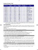
Страница 9: ...Supports Multiple VGA Modes Refer to the Standard Timing Table for a listing of modes supported by this LCD Monitor PROBLEM Picture is unclear and unstable The picture is unclear and unstable please perform the following steps 1 Enter PC to Shut Down Windows status while you re in MS Windows environment 2 Check the screen to see if there s any black vertical stripes appear If there are take advant...

Отзывы: