background image

Test Devices

The touch computer can be pre-installed with several different hardware options. To test an 
optional device that is installed on the touch computer, follow the instructions below.

NOTE

: Testing icons are located on the desktop. Testing of a particular device can only be  

done after the device is properly installed.

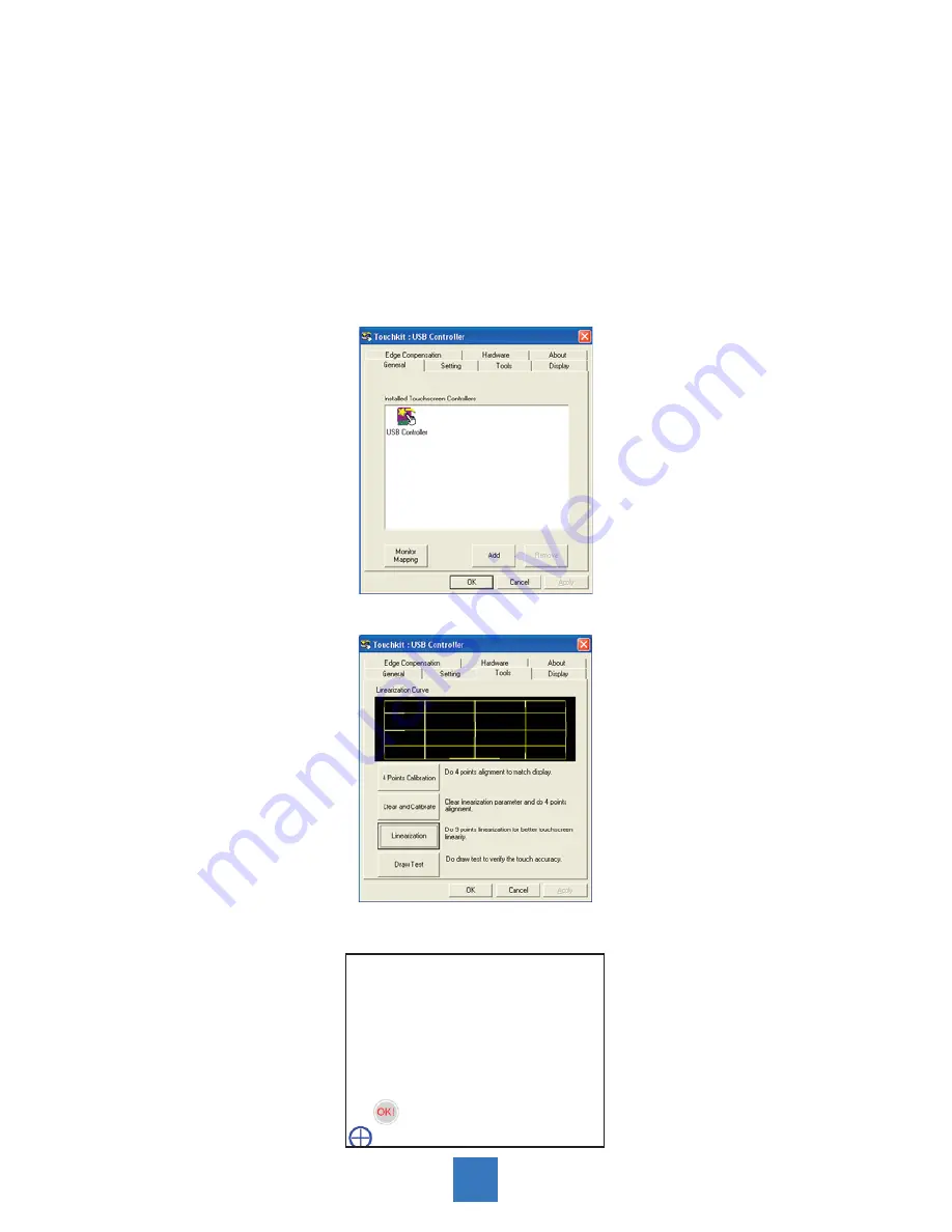
Testing the Touchscreen

The touchscreen is pre-calibrated for accurate touch response.

Calibration* 

If for any reason the touchscreen needs to be re-calibrated, double-click the Touchscreen-test 

icon. The window shown below will open.


17

→→

Содержание PA1575R

Страница 1: ...PA1575R All in One Touchscreen Computer USER S GUIDE www planartouch com...

Страница 2: ...to follow the user s manual to install or use this device might produce harmful interference with radio communication Not withstanding the foregoing it does not guarantee that this type of harmful in...

Страница 3: ...Controls 9 Initial Turn On 10 XP PRO Initial On Steps 10 Test Devices 17 Testing the Touchscreen 17 Recovering the Operating System 18 1 Using the Recovery CD 18 2 PA1575R Touchscreen Driver Install...

Страница 4: ...mercial cleaners or 50 50 mixture of water and isopropyl alcohol Use a soft cloth moistened with mild detergent to clean the display housing Use only high quality and safety approved AC DC adapter Dis...

Страница 5: ...orts USB 2 0 Ext x 3 Int x 4 2 x DB9 for COM1 COM2 1 x Digital displays DVI D 1 x Line out 1 x 12V power jack 1024x768 XGA resolution 15 viewable display area Kensington security slot 75 mm VESA mount...

Страница 6: ...ackage Overview LCD Touch Computer Power Cord Recovery CD Touch Screen Driver Installation CD ROM DC Power Supply Landing Strip User s Guide xxxxxxxxx xxxxxxxxx xxxxxxxxx USER S GUIDE www planartouch...

Страница 7: ...Installation Product Overview Front View Button View Without Stand RJ 45 DVI RS 232 USB AUDIO DC IN 4...

Страница 8: ...ion of the arrow 2 Connect applicable cables to the appropriate connectors 3 Re attach the stand back cover by pressing firmly until the tabs snap into place You may also keep the cables in order by u...

Страница 9: ...Kensington Security Slot The computer can be secured to your desk or any other fixed object with Kensington lock security products The Kensington lock is not included 6...

Страница 10: ...computer on a swing arm or other mounting fixture follow the instructions included with the mounting fixture to be used please note to mount touch computer to the devices either mounting fixture or sw...

Страница 11: ...Remove the Deskstand Remove stand back cover 1 Remove hinge cover 2 Remove 4 screws and then 3 remove hinge 8...

Страница 12: ...Name Menu Up Down Enter Power OSD Key Menu off status Menu on status Menu appear Menu disappear return to main item Brightness Main item select up Adjust up Mute Main item select down Adjust down Ent...

Страница 13: ...10 minutes Additional time may be needed depending on touch computer hardware configuration and connected devices To setup the Windows OS for the touch computer turn on the touch computer and follow...

Страница 14: ...Step 2 Press Next Step 3 Read agreement and press I accept this agreement and Next 11...

Страница 15: ...Step 4 Language Selection Press Next Click Customize The Regional and Language window shown below will appear Step 5 Type your full name organization and press Next 12...

Страница 16: ...Step 6 Type product key and press Next Please find the Certificate of Authenticity license label on the back cover 13...

Страница 17: ...Step 7 Setup your computer name administrator password and press Next Step 8 Date and Time Settings Setup your computer date and time and press Next 14...

Страница 18: ...Step 9 Choose typical or custom setting and press Next Step 10 Choose applicable option 15...

Страница 19: ...Step 11 Press Finish Step 12 Finish and launch windows system 16...

Страница 20: ...tions below NOTE Testing icons are located on the desktop Testing of a particular device can only be done after the device is properly installed Testing the Touchscreen The touchscreen is pre calibrat...

Страница 21: ...e on screen instructions to complete recovery NOTE All data will be deleted during the recovery process User must back up files prior to recovering the operating system 1 Using the Recovery CD For XP...

Страница 22: ...Step 4 Press any key to continue 19...

Страница 23: ...Step 5 Press any key to continue 20...

Страница 24: ...Step 6 Press Next Step 7 Read agreement and press I accept this agreement and Next 21...

Страница 25: ...Step 8 Press Next Step 9 Type your full name organization and press Next 22...

Страница 26: ...Step 10 Type product key and press Next Please find the Certificate of Authenticity license label on the back cover 23...

Страница 27: ...Step 11 Setup your computer name administrator password and press Next Step 12 Setup your computer date and time and press Next Step 13 Choose typical or custom setting and press Next 24...

Страница 28: ...Step 14 Choose applicable option Step 15 Press Finish Step 16 Finish and launch windows system 25...

Страница 29: ...tems Windows XP Step 1 Insert the included Touchscreen disk into an external DVD ROM sold separately Step 2 Select the monitor size 15 and then model name PA1575R Step 3 Click on the Load Driver butto...

Страница 30: ...ating Temperature Independent of altitude 20 o C to 60 o C Humidity Operating non condensing 20 to 80 Non Operating 38 7 o C maximum wet bulb temperature 10 to 90 Altitude Ranges Operating 0 to 12 000...

Страница 31: ...ck Caution Risk of Explosion if Battery is replaced by an Incorrect Type Dispose of Used Batteries According to the Instructions Storage XP SATA 2 5 HDD 160GB or above Power supply Type External brick...

Страница 32: ...XGA 1024 x 768 Display Color 16 2 million color Plug Play DDC 2B Power Supply Specifications The touch computer shall be powered by 12VDC from a universal type power supply brick with the following ch...

Страница 33: ...eral Options and Upgrades May vary Battery Notice Caution Risk of explosion if battery is replaced by an incorrect type Dispose of used batteries according to the instructions COM1 COM2 Connector RS23...

Страница 34: ...LAN connector Pin Definition 8 1 Pin Signal Name 1 TD 2 TD 3 RD 6 RD Power Input Pin Definition 1 2 Pin Signal Name 1 12V 2 Ground USB Pin Definition 1 2 3 4 Pin Signal Name 1 5V 2 USB D 3 USB D 4 GN...

Страница 35: ...2 2 DATA 2 3 Shield 2 4 4 DATA 4 5 DATA 4 6 DDC CLOCK 7 DDC DATA 8 VSYNC 9 DATA 1 10 DATA 1 11 SHIELD 1 3 12 DATA 3 13 DATA 3 14 DDC POWER 15 A GROUND 1 16 HOT POWER 17 DATA 0 18 DATA 0 19 SHIELD 0 5...

Страница 36: ...en Check that all the I O and power connectors are correctly and well connected described in the Installation section Make sure the pins of the connectors are not crooked or broken Problem Partial Ima...

Страница 37: ...34 Product Dimensions 364 0 mm 295 0 mm 321 9 mm 176 3 mm 69 0 mm 240 0 mm 206 1 mm Side View Top View Front View...

Страница 38: ...Compatibility Modes Mode Resolution H Frequency KHz V Frequency Hz VGA 720 x 400 31 47 70 VGA 640 x 480 31 47 60 VESA 800 x 600 37 88 60 VESA 1024 x 768 48 36 60 35...

Страница 39: ...itor touch screen or other Planar products visit our online store at www PlanarOnline com or find other stores who carry Planar products at http www planar com howtobuy Technical Support Visit Planar...

Страница 40: ...LANAR1 866 752 6271 or 1 503 748 5799 outside the United States Hours 24 hours a day 7 days a week 2011 Planar Systems Inc 5 11 Planar is a registered trademark of Planar Systems Inc Other brands and...

Отзывы: