EL640.200-SK Operations Manual (020-0348-00B)
8
Connector
Video signals and DC power are connected to the display through a 24-contact
dual-row 2 mm square pin locking connector, Samtec EHT-112-01-S-D. The
mating connector is available through Samtec as an IDC cable assembly (Series
TCSD-12-S-XX-01-X-X). The proper connector, user-specified cable length, and
connector configuration are supplied as a single unit. Consult your Samtec
representative (1-800-SAMTEC9) for cable and connector options.
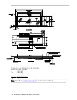
Figure 2. Data/Power Connector.
Table 4. Connector Pinouts.
Pin
Signal
Description
Pin
Signal
Description
1
VID1 (U1)
Video Data
2
VID0 (U0)
Video Data
3
VID3 (U3)
Video Data
4
VID2 (U2)
Video Data
5
VID (L3)
Video, Lower Panel
6
VID (L2)
Video, Lower Panel
7
VID (L1)
Video, Lower Panel
8
VID (L0)
Video, Lower Panel
9
VCLK
Video Clock
10
GND
Ground
11
HS
Horizontal Sync
12
GND
Ground
13
VS
Vertical Sync
14
GND
Ground
15
Selftest
Selftest Input
16
GND
Ground
17
VL (+5V)
+5 V Power
18
VIDMODE
Selects video mode
19
VH (+12V)
+12 V Power
20
VH (+12V)
+12 V Power
21
LUM 0
Digital dimming
22
LUM1
Digital dimming
23
GND
Ground
24
LUMA
Analog dimming input
(Viewed from top of connector)
Key
Pin 2
Pin 1
Pin 1
Key
(Viewed from electronics side of display)


