background image


EL512.256-H Series Operations Manual (020-0354-00A)


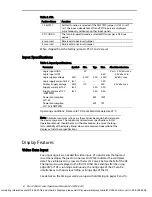
Table 3. PS1. 

Position Name 

Function 

1   SELFTST 

Self test function is selected, if theSELFTEST jumper is OFF. In self 
test,


the input video data at VID and TVID inputs are displayed 

asynchronously without any other input signals. 

2   DCONFIG 

The Two-bits-parallel mode is selectedif this jumper is OFF (see 
page 8) 

3   reserved 

Reserved, do not insert jumper. 

4   reserved 

Reserved, do not insert jumper. 

When shipped from the factory, jumpers PS1/1 and 2 are set. 

Input Specifications 

Table 4. Input Specifications. 

Parameter 

Symbol 

Min. 

Typ. 

Max.   

Absolute min./max. 

Logic input HIGH 
Logic input LOW 


Logic supply voltage 
Logic supply current at 5V 
Display Supply voltage 
Supply current at 12V 


Supply current at 12V    
(LOWPWR) 
Power consumption 
5V/12V 
Power consumption 
5V/12V (LOWPWR) 


Vcc1 
Icc1 
Vcc2 
Icc2 
Icc2 

2V 
 

4.75V 
— 
11V 


5.0V 
— 
— 
0.5A 
0.3A 
 
6W 
 
4W 


0.8V 
5.25V 
0.2A 
30V 
0.9A 
0.5A 
 
12W 
 
7W 

Vcc1 + 0.5V abs. max. 

–0.5V abs. min. 

6V abs. max. 


33V abs. max. 

Operating conditions: Frame rate 70 Hz. ambient temperature 25°C. 

Note:  Absolute maximum ratings are those values beyond which damage to 
the device may occur. The minimum and maximum specifications in this 
Operations Manual should be met, without exception, to ensure the long-
term reliability of the display. Planar does not recommend operation of the 
display outside these specifications. 


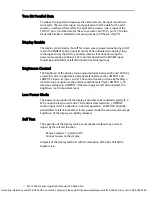
Display Features  

Video Data Input


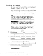
Four input signals are needed for video input. VS signal marks the topmost 
row, HS envelopes the pixels


in one row and VCLK indicates the valid pixel 

data. The


visible pixels in a row are the last 512 pixels before the


fall of the HS. 

The topmost row displayed is the first HS


HIGH time ending after the rising 

edge of VS. If HS is


running continuously, the rising edge of the VS can be


simultaneous to the previous falling or rising edge of the HS. 

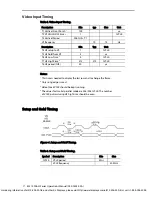
See details on the timing as well as setup and hold timing on pages 9 and 10. 

For ordering information of el512-256-h3-frb and other EL Displays, please visit http://www.eldisplays.com/el512-256-h3-frb/ or call +1-888-394-4998.

Содержание EL512.256-H Series

Страница 1: ...s 512 x 256 Pixel Electroluminescent Display USER S MANUAL www planar com For ordering information of el512 256 h3 frb and other EL Displays please visit http www eldisplays com el512 256 h3 frb or ca...

Страница 2: ...tion April 1995 Document number PI02552 Ver 1 June 2004 Document number 020 0354 00A For ordering information of el512 256 h3 frb and other EL Displays please visit http www eldisplays com el512 256 h...

Страница 3: ...f Test 8 Installation and Handling 9 Video Input Timing 10 Setup and Hold Timing 10 Operational Specifications 11 Environmental 11 Reliability 11 Safety 11 Optical 12 Display Colour 12 Optional Filter...

Страница 4: ...d Side Views with FRB Steel Mounting Frame 17 Tables Table 1 Input to the Display 5 Table 2 Connectors 6 Table 3 PS1 7 Table 4 Input Specifications 7 Table 5 Video Input Timing 10 Table 6 Setup and Ho...

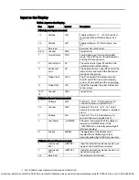
Страница 5: ...displays require 5 Vdc and 11 30 Vdc power input and four basic input signals to operate 1 Video Data or pixel information 2 Video Clock pixel clock or dot clock 3 Horizontal Sync 4 Vertical Sync EL T...

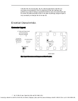
Страница 6: ...tage is applied to both the correct row electrode and the correct column electrode to cause a lit pixel Operating voltages required are provided by an integral DC DC converter Electrical Characteristi...

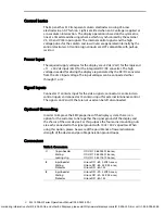
Страница 7: ...al that supplies the pixel information to the system 12 14 16 Ground GND Signal return J2 Optional power input connector 1 Voltage Vcc2 Same as J1 Pins 1 2 not necessary to connect if power is supplie...

Страница 8: ...nput for the video signals connector J2 contains two control inputs and connector J3 contains input for external luminance control The signals on J2 and J3 that are not used can be left disconnected O...

Страница 9: ...0 5V abs min 6V abs max 33V abs max Operating conditions Frame rate 70 Hz ambient temperature 25 C Note Absolute maximum ratings are those values beyond which damage to the device may occur The minim...

Страница 10: ...d 100 by an external 50 k logarithmic potentiometer between the LUMPOT1 and LUMPOT 2 inputs J3 pins 1 and 2 The control function is done by feeding a small DC current signal via the external potentiom...

Страница 11: ...display input connector is recommended If longer cables up to 2m 80 in length are needed a serial resistor of appr 47 could be placed at each of the four signal line outputs of the transmitter in orde...

Страница 12: ...period tHS 50 s Notes 1 This time is needed to display the last row and to change the frame 2 Only rising edge is used 3 Video Clock VCLK should be kept running 4 The values for two bit parallel mode...

Страница 13: ...68 2 3 Damp Heat 25 55 C 95 RH Non operating IEC 68 2 30 Altitude Operating 15 000 m 50 000 ft above sea level Vibration 20 500 Hz ASD level 0 05 G2 Hz Random vibration wide band IEC 68 2 36 Test Fdb...

Страница 14: ...ter and four corners Luminance Variation Time Maximum 20 10 000 h Luminance Variation Temperature Typical Maximum 10 15 over 25 65 C range Viewing Angle Minimum 160 Optional Filter For best overall op...

Страница 15: ...rea Characteristics Active Area millimeters inches height 97 5 3 84 width 195 1 7 68 Pixel Pitch millimeters inches height 0 381 0 015 width 0 381 0 015 Pixel Size millimeters inches height 0 25 0 01...

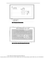
Страница 16: ...0354 00A 13 Fig 5 Viewing Area Characteristics Fig 6 Front View without Mounting Frame standard For ordering information of el512 256 h3 frb and other EL Displays please visit http www eldisplays com...

Страница 17: ...perations Manual 020 0354 00A 14 Fig 7 Back and Side Views Dimensions in mm For ordering information of el512 256 h3 frb and other EL Displays please visit http www eldisplays com el512 256 h3 frb or...

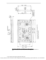
Страница 18: ...020 0354 00A 15 Fig 8 Back and Side Views with FRA Aluminum Mounting Frame Dimensions in mm For ordering information of el512 256 h3 frb and other EL Displays please visit http www eldisplays com el5...

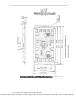
Страница 19: ...l 020 0354 00A 16 Fig 9 Back and Side Views with FRB Steel Mounting Frame Dimensions in mm For ordering information of el512 256 h3 frb and other EL Displays please visit http www eldisplays com el512...

Страница 20: ...ted insufficient Seller shall refund Buyer s paid price for the Goods and have no other liability to Buyer All warranty repairs must be performed at Seller s authorized service center using parts appr...

Страница 21: ...ark the outside of the shipping container with the RMA number Ordering Information Product Part Number Description EL512 256 H2 E0051240022 0 55 C operating temperature range EL512 256 H2 FRA E0051240...

Страница 22: ...nland Tel 358 9 420 01 Hours M F 7 00am 4pm CET 2004 Planar Systems Inc 06 04 Planar is a registered trademark of Planar Systems Inc ICE ICEBrite and ICEPlus are trademarks of Planar Systems Inc Other...

Отзывы: