background image

Page 3

For technical questions, please call 1-888-866-5797.

Item 69521 
        

ASSEMBLY INSTRUCTIONS

Read the ENTIRE IMPORTANT SAFETY INFORMATION section at the 
beginning of this document including all text under subheadings therein 
before set up or use of this product.

Left Leg 

Wheel

Detail

Left & Right 

Legs (1,9)

Mounting

Plate (6)

Long & Short 

Arms (8, 7)

Column (4)

Base (2)

Figure A:  Overall Assembly

Step 1

Step 2

Step 4

Step 3

Figure B:  Steps 1 through 4

1.  Place the Right and Left Leg (1, 9) 

pieces into the Base (2), lining up the 
holes on the sides. Secure in place with 
the Leg Lock Pins (15) and R-Pins (16).

Note:

 The wheel housing of the Right 

and Left Legs (9, 1) are welded at an 
angle from the Legs and are different from 
each other. Be sure to insert the Legs into 
the Base so that the wheels will be parallel, 
pointing forward, not out to the sides. 

2.  Attach the Column (4) to the Base (2),  

using the Bolts, Washers and Nuts (14).  
Do not fully tighten the Bolts 
in place until Step 4.

3.  Align the holes of the Braces (3) on 

either side of the Column (4) hole 
and secure with the Bolts, Washers 
and Nuts (13). Do not fully tighten 
the Bolts in place until Step 4.

4.  Align the bottom of the Braces (3) 

with the holes on the inside of the 
Base (2) frame and secure with 
the Bolts, Washers and Nuts (17). 
Tighten all Bolts from Steps 2 through 4.

Handle (5)

Short 

Arm (7)

Long Arm (8)

Bolt, Washer, 

Nut (10)

Mounting 

Plate (6)

Pin (12)

Column (4)

Figure C:  Mounting Plate Installation

5.  Grease the Mounting Plate (6) shaft 

using chasis grease (sold separately).

Содержание 69521

Страница 1: ...ence 20c When unpacking make sure that the product is intact and undamaged If any parts are missing or broken please call 1 888 866 5797 as soon as possible Copyright 2012 by Harbor Freight Tools All...

Страница 2: ...roperty damage 1 Study understand and follow all instructions before operating this device 2 Do not exceed rated capacity Be aware of dynamic loading Sudden load movement may briefly create excess loa...

Страница 3: ...welded at an angle from the Legs and are different from each other Be sure to insert the Legs into the Base so that the wheels will be parallel pointing forward not out to the sides 2 Attach the Colu...

Страница 4: ...ollar of the Column 4 Align the holes and insert the Pin 12 7 Slide off one of the Handle 5 rubber grips and insert the Handle 5 through the large holes at the end of the Mounting Plate 6 post Replace...

Страница 5: ...e 6 side and securely tighten them into the engine The bolt heads must press against the back of the Arms if needed use flat washers not included as spacers 6 Tighten the Bolts 10 and Nuts that hold t...

Страница 6: ...n and free of dirt or grease 3 Before each use check that hardware is securely fastened 4 Check that the Casters are clean and turn properly 5 AFTER USE clean external surfaces of the stand with a cle...

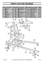
Страница 7: ...Short Arm 2 8 Long Arm 2 9 Right Leg 1 Part Description Qty 10 Bolt Set M14 x 70 4 11 Big Washer 15 4 12 Pin 1 13 Bolt Set M14 x 70 1 14 Bolt Set M14 x 90 2 15 Leg Lock Pin 4 16 R pin 4 17 Bolt Set M...

Страница 8: ...epairs or alterations outside our facilities criminal activity improper installation normal wear and tear or to lack of maintenance We shall in no event be liable for death injuries to persons or prop...

Отзывы: