background image

27 


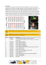
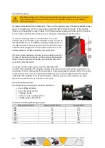
Fuse holder


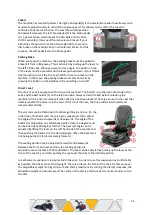
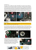
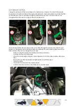
The fuse holder is positioned on the left-hand side of the wheelhouse. The fuses are protected 
against moisture and dust by a transparent protective cover. When checking or replacing a fuse, this 
protective cover must be removed. After checking or replacing, the protective cover must be 
reattached. The type of fuse used in the fuse holder is standard (auto) plug-in fuses type normal 
(length of 19.1 mm). The main fuse is of the maxi type (length of 29.2 mm). To reach the main fuse, 
the cover under the joystick must be removed. To do this, four bolts must be loosened, two at the 
top and two at the front. Next, the post must be released from the ROPS frame on the right front, 
this can be done by loosening two bolts at the bottom of the post. By pushing these up and sideways, 
the failure protection can be pushed all the way to the front. The cover can now be lifted off. 


WARNING! Switch off the battery isolator if you want to check or replace the fuses. 


WARNING! Never install a fuse with a higher amperage, as this will damage electrical 
components and may cause fire and explosion.  


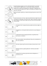
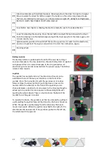
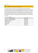
Fuse 

Current 

Application 

5 ampere 

Power supply indicator lights and meters dashboard. 

15 ampere 

Power supply brake light relays, pressure sensors, stop magnet and 
diesel pump. 

15 ampere 

Power supply hazard lights. 

10 ampere 

Power supply front work light. 

10 ampere 

Power supply flashing light. 

10 ampere 

Power supply rear work lights. 

10 ampere 

Power supply locking differential. 

10 ampere 

Power supply brake pressure sensor, speed sensor and alternator. 

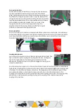
15 ampere 

Power supply indicators. 

10 

30 ampere 

Power supply controller. 

11 

10 ampere 

Power supply coil handbrake and coil 6/2 valve. 

12 

10 ampere 

Power supply neutral switch. 

13 

10 ampere 

Power supply horn. 

14 

10 ampere 

Power supply sidelight, dashboard and license plate lighting. 

15 

10 ampere 

Power supply low beam. 

16 

10 ampere  

Power supply high beam. 

17 

40 ampere  

Main fuse. 


Содержание X24-36

Страница 1: ...Pitbull Compact Loaders Operator s manual...

Страница 2: ......

Страница 3: ...andbouwmachines B V reserves the right to change parts at any time without prior or direct notification to the buyer The contents of this operator s manual may also be changed without prior notificati...

Страница 4: ...s 19 5 Operation of the machine 20 6 Making the machine ready for use 26 7 Commissioning of the machine 29 8 Maintenance 32 8 1 Periodic maintenance schedule 32 8 2 Service areas 34 8 3 Lubrication po...

Страница 5: ...ttery 42 8 19 Article numbers 42 9 Damage and malfunctions 43 9 1 Damage repair 43 9 2 Towing 43 9 3 Hoisting 43 9 4 Troubleshooting list 45 10 Servicing 48 11 Fluids Specification Sheets 52 Index 67...

Страница 6: ...document is an integral part of the machine and must always be present with the machine to provide the correct information about the machine The most recent version can be requested from your dealer a...

Страница 7: ...must be used are included in the parts list The parts book can be downloaded via www pitbull loader com under Support The user statement below has not been fully completed signed scanned and sent to...

Страница 8: ...tioned manufacturer s site The undersigned hereby declares that the machine Brand Pitbull Models X24 36 X24 45 X27 36 X27 45 Category Compact wheel loader articulated loader shovel earth moving machin...

Страница 9: ...rocedures carefully Fatal hazard there is a direct risk of your getting killed CAREFUL CAREFUL The machine may be damaged if you do not carry out the procedures carefully NOTE NOTE A remark with addit...

Страница 10: ...n a trailer It is not permitted to use the Pitbull for the following operations Transporting animals Carrying persons other than the driver Transport of hazardous substances and products containing ha...

Страница 11: ...ission According to the Working Conditions Act the machine is considered lifting and hoisting equipment which means that it may only be operated by persons who have specific expertise for this purpose...

Страница 12: ...the stickers must always be clean and clearly legible always replace any stickers that are damaged They are available from your dealer 1 2 3 1 Crushing hazard near the mixing compartment Keep your dis...

Страница 13: ...88 dB 5 6 7 Hoisting point Attach the lifting equipment only in these places Danger of head injury Keep sufficient distance from the boom Danger of crushing at the hinged parts of the boom Keep suffi...

Страница 14: ...fluids under pressure Explosion and shock hazard Ensure adequate ventilation when charging the battery and do not short circuit 13 4 13 5 13 6 Danger of crushing Keep distance from the fan when it has...

Страница 15: ...15...

Страница 16: ...16 Green indicates that the position of the sticker is not visible on the image but is between the boom Inner sides of bonnets...

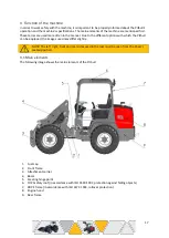
Страница 17: ...hich the Pitbull can be equipped the images used may differ slightly NOTE The left right front and rear sides used in the text must be seen from the driver s seated position 4 1 Main elements The foll...

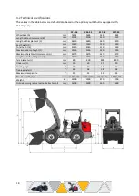
Страница 18: ...D mm 1240 1240 1240 1240 Total height E mm 2140 2140 2140 2140 Maximum dump height F mm 2250 2250 2250 2250 Maximum height with implement G mm 3270 3270 3270 3270 Height up to the lifting pin H mm 283...

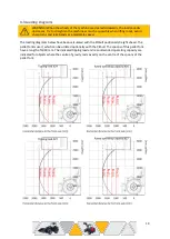
Страница 19: ...t a moderate speed The loading diagrams below have been calculated with the Pitbull positioned straight ahead The pallet fork is used which can be ordered optionally with the Pitbull The spoons of thi...

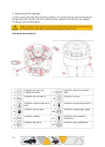
Страница 20: ...ls before starting to work with the machine If you have to do this while working it will be too late Wheelhouse with dashboard 1 Indication alternator not charging the battery 7 Indication indicator a...

Страница 21: ...nk and a quarter filled tank to indicate that refuelling is required Never empty the tank this is bad for the fuel filter and fuel pump 16 Work lights front Pressing this button switches the front wor...

Страница 22: ...ise to the stop protection the electrical system is supplied with power When it is turned clockwise to the stop protection all electronic systems are disconnected from the power supply The Battery iso...

Страница 23: ...the belt before unlocking the machine s drive and only release it when the drive has been locked There is a sensor in the seat that detects whether the driver is in the seat If this is not the case th...

Страница 24: ...must be pushed forward When you want to leave the machine you must lock the drive and only then slide the failure protection backwards Coupling attachments Just in front of the joystick is a lever th...

Страница 25: ...d pin is 3840 kg on the Pitbull X24 and 3660 kg on the Pitbull X27 Make sure that a breakaway cable is attached by an auxiliary coupling and that it lies in a noose around the ball when pulling a trai...

Страница 26: ...naked flames are prohibited when refuelling Switch off the engine before refuelling and make the Pitbull free of flammable substances Tyre pressure The correct tyre pressure is of great importance to...

Страница 27: ...be lifted off WARNING Switch off the battery isolator if you want to check or replace the fuses WARNING Never install a fuse with a higher amperage as this will damage electrical components and may ca...

Страница 28: ...tick The dipstick uses dashes to show the minimum and maximum levels for the engine oil level Make sure that the engine oil level is just below the maximum engine oil level when the machine is put int...

Страница 29: ...ing points of attention Check that the belt is fastened and the failure protection is extended Adjust the position of the seat to the ideal sitting position for the driver Make sure that the exhaust f...

Страница 30: ...evenly while driving Steer less sharply when driving over uneven or rough surfaces NOTE Avoid steering when the machine is stationary If you steer when the machine is stationary the tyres will wear o...

Страница 31: ...slow down while still being lubricated and the lubricating oil to remain cooled This increases the service life of the turbo bearings To prevent theft switch off the machine s ignition and do not lea...

Страница 32: ...ator Take into account any pressure that may still be present in the hydraulic system Always wear the correct personal protective equipment and work in a well organised and clean environment Only clea...

Страница 33: ...engine oil Change engine oil Check level and quality of coolant Replace coolant Check cyclone filter Replace engine oil filter Check combination cooler Check air filter Check fuel filter Check V belt...

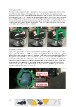
Страница 34: ...tor is off before opening this service area The drive can be reached via the service area under the seat 3 To reach it the bolts on the sides of the seat must be loosened There is one on each side Onc...

Страница 35: ...side of the engine compartment against the inside of the wheel arch Unscrew the green cap for topping up Old brake fluid can be replaced by letting it flush through the bleed nipple 1 at the brake cal...

Страница 36: ...the wheel hubs 1 0 litre of fresh oil is required per wheel hub 8 9 Rear axle oil Changing the oil on the rear axle is done in the same way with both the 45 lock function and the open differential on...

Страница 37: ...ING Do not open the cap of the combination cooler if the coolant can be hot Due to the pressure the hot liquid may escape The coolant that is used is XLC which can be used throughout the year in a 50...

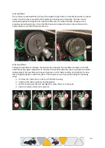
Страница 38: ...r works optimally and the part must be replaced 8 13 Motor oil filter Replace the engine oil filter according to the maintenance schedule this is necessary to protect the engine against dirt The engin...

Страница 39: ...e lock 8 15 Fuel filter Change the fuel filter according to the maintenance schedule The fuel filter is located on the left hand side of the engine compartment Unscrew the fuel filter with filter plie...

Страница 40: ...mination in the hydraulic tank and in the filtration system Check the hydraulic oil level using a flashlight by looking in the hydraulic tank The maximum level is up to the edge of the filling neck Re...

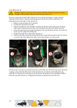
Страница 41: ...the drive motor is accessible through the service area under the seat Make sure the ignition and the battery isolator are switched off create working space around the filter and clean the area Go thro...

Страница 42: ...t the battery to a trickle charger Always disconnect the negative pole first and then the positive pole When replacing the battery terminals first secure the positive pole and then the negative pole W...

Страница 43: ...rable dangerous objects Keep sufficient distance from the above so that the machine cannot fall against or onto these if a hoisting cable or round sling breaks or tears off It is best to lift the mach...

Страница 44: ...sting cables or round sling so that they do not touch the roof This can damage the roof and the license plate holders If the machine is tilted or sagging it could be that the hoisting chains or slings...

Страница 45: ...engine gets too hot Not enough engine oil Top up the engine oil Wrong engine oil Drain the engine oil and top it up with the correct engine oil Engine oil pressure too low Check the engine oil filter...

Страница 46: ...he hydraulic oil Air in the hydraulic system Move the boom up a little more if it is already at the highest position Wrong hydraulic oil Drain the hydraulic oil and fill the tank with the correct hydr...

Страница 47: ...k the return line Hydraulic oil comes out of the vent There is too much hydraulic oil in the system Make sure all cylinders are retracted and drain the hydraulic oil until the level has dropped to the...

Страница 48: ...rs after the last major maintenance Light maintenance at 250 working hours after the last major maintenance Major maintenance at 750 working hours or after 1 year whichever is reached first Light main...

Страница 49: ...t 500 working hours after the last major maintenance Light maintenance at 250 working hours after the last major maintenance Major maintenance at 750 working hours or 1 year after the last major maint...

Страница 50: ...ing hours or 1 year after the last major maintenance Light maintenance at 500 working hours after the last major maintenance Light maintenance at 250 working hours after the last major maintenance Maj...

Страница 51: ...working hours after the last major maintenance Major maintenance at 750 working hours or 1 year after the last major maintenance Light maintenance at 500 working hours after the last major maintenanc...

Страница 52: ...52 11 Fluids Specification Sheets Brake fluid...

Страница 53: ...53...

Страница 54: ...54 Lubricating oil...

Страница 55: ...55...

Страница 56: ...56...

Страница 57: ...57 Motor oil...

Страница 58: ...58...

Страница 59: ...59...

Страница 60: ...60 Coolant...

Страница 61: ...61...

Страница 62: ...62...

Страница 63: ...63 Hydraulic oil...

Страница 64: ...64...

Страница 65: ...65 Lubricating grease...

Страница 66: ...66...

Страница 67: ...ation 11 Liability 7 Loading Diagrams 19 Lubricating grease 65 Lubricating oil 55 Lubrication 28 Lubrication points 34 Main elements 17 Maintenance 32 Motor oil 37 58 Motor oil filter 38 Oil front axl...

Страница 68: ...68 Notes...

Страница 69: ...69...

Страница 70: ...70...

Страница 71: ...www peetersgroup com...

Отзывы: