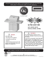
Скачайте бесплатное руководство по сборке Pit Boss 10534 с нашего веб-сайта. Этот уникальный продукт обеспечит вам все необходимые инструкции для сборки вашего гриль-мангала. Не упустите возможность скачать его прямо сейчас с manualshive.com.
Страница 1: ...ire manual before installation and use of this electric pellet fuel burning appliance Failure to follow these instructions could result in property damage bodily injury or even death Contact local building or fire officials about restrictions and installation inspection requirements in your area AVERTISSEMENT Veuillez lire l intégralité du manuel avant l installation et l utilisation de cet appare...
Страница 2: ...am 8pm PST EN FR ES Toll Free 1 877 303 3134 Fax 1 877 303 3135 Parts Specs 4 Assembly Preparation 6 Assembly Instructions Mounting The Wheels To The Legs 6 Assembling The Cart 6 Mounting The Cart Panels 7 Installing The Cart To The Barrel 7 Securing The Door Stopper Door Magnet 8 Attaching The Cabinet Door Handles 8 Mounting The Cabinet Doors To The Cart 8 Attaching The Lid Handle 9 Securing The ...
Страница 3: ...me Broiler Adjusting Bar x1 27 Door Magnet x1 28 Door Stopper x1 29 Cabinet Door Handle x2 30 Cabinet Door Handle Bezel x4 31 Cabinet Door Left x1 32 Cabinet Door Right x1 33 Bottom Shelf x1 Part Description 34 Cart Panel Back x1 35 Cart Panel Side x2 A Screw x24 B Washer x24 C Locking Washer x24 D Screw x14 NOTE Due to ongoing product development parts are subject to change without notice Contact...
Страница 4: ...ENGLISH 5 PARTS SPECS D C B A 1 2 5 4 12 13 14 15 16 19 18 20 25 26 27 28 29 30 31 32 34 33 35 24 21 7 8 11 3 17 23 9 10 22 6 ...
Страница 5: ...ocking washers and screws Note illustration for support leg placement On a level surface continue to secure the other support legs to the bottom shelf IMPORTANT The edge of the bottom shelf with holes should face forward The holes are for the cabinet doors installation ASSEMBLY PREPARATION Parts are located throughout the shipping carton including underneath the grill Inspect the grill parts and h...
Страница 6: ...ching the unit and parts during assembly Open the main grill lid and remove the the large diffuser plate from the bottom of the main grill barrel This part will be re installed on a later step Note 4A Lay the main barrel on its side hopper end pointed upward on the cardboard Note illustration 4B Insert the assembled cart into the main barrel brace and secure each leg to the main barrel brace using...
Страница 7: ...rt one screw so that it protrudes to the front Add a cabinet door bezel on the screw then hand tighten the screw from the rear into the cabinet door handle Continue to secure the handle by inserting a screw into the other side and tightening Repeat same installation for second cabinet door handle 7 MOUNTING THE CABINET DOORS TO THE CART Installation Align the left cabinet door with the front of th...
Страница 8: ...on the top of the main barrel 10 MOUNTING THE SIDE SHELF HANDLE SERVING TRAY Parts Required 2 x Serving Tray Handle 15 1 x Serving Tray 16 1 x Side Shelf Handle 17 Installation Remove the four pre installed screws from the side of the main barrel Mount the side shelf handle onto the main barrel using four screws previously removed Mount serving tray handles to serving tray using the two pre instal...
Страница 9: ...chimney opening on the side of the main barrel Remove the pre installed screws From the outside of the main barrel secure the chimney gasket and chimney stack to the side panel by re installing the two screws The screw will fasten to the pre mounted nut on the inside of the barrel Next secure the chimney cap onto the top of the chimney stack with the screw and nut NOTE Adjust the chimney cap to af...
Страница 10: ...e the flame broiler slider on top of the flame broiler main plate covering the slotted openings Ensure the raised tab is on the left Note 14C First remove the flame broiler adjusting bar handle from the flame broiler adjusting bar Insert the flame broiler adjusting bar through the opening hole on the left side of the main barrel Add the flame broiler adjusting bar handle back onto the end outside ...
Страница 11: ... outlet is highly sensitive to power surges it will likely trip during the start up phase of operation During the start up phase the igniter draws 200 700 watts of electricity which can be too much power for a GFCI outlet to handle Each time it trips it increases in sensitivity If the GFCI keeps tripping replace the outlet or change to a non GFCI outlet ON THE ROAD Disconnect the igniter from the ...
Страница 12: ... Installer le plateau à graisse 20 Fixer la cheminée 20 Installation de l ouvre bouteille 20 Installer les composants de cuisson 21 Connexion à une source d alimentation 22 AVIS SUR LES DROITS D AUTEUR Droit d auteur 2020 Tous droits réservés Nulle partie de ce manuel ne peut être reproduite transmises transcrite ou stockée dans un système de recherche de quelque façon que ce soit sans l autorisat...
Страница 13: ...réglage pour chaudière x1 27 Aimant de porte x1 28 Butée de la porte x1 29 Poignée de porte de l armoire x2 30 Cadran de la poignée de porte de l armoire x4 31 Porte de l armoire gauche x1 32 Porte de l armoire droite x1 No Description des pièces 33 Étagère inférieure x1 34 Panneau du chariot arrière x1 35 Panneau du chariot latéral x2 A Vis x24 B Rondelle x24 C Rondelle de verrouillage x24 D Vis ...
Страница 14: ...FRANÇAIS 15 PIÈCES ET SPÉCIFICATIONS D C B A 1 2 5 4 12 13 14 15 16 19 18 20 25 26 27 28 29 30 31 32 34 33 35 24 21 7 8 11 3 17 23 9 10 22 6 ...
Страница 15: ...ondelles de blocage et vis Notez l illustration du placement des pieds de support Sur une surface plane continuez à fixer les autres pieds de support à l étagère inférieure IMPORTANT Le bord de l étagère inférieure avec des trous devrait faire face vers l avant Les tous sont destinés à l installation des portes de l armoire 1 20 21 24 22 23 PRÉPARATION DE L ASSEMBLAGE Les pièces sont situées dans ...
Страница 16: ...cle du gril principal et retirez la grande plaque de diffusion située au bas du corps du gril principal Cette partie sera réinstallée à une étape ultérieure Remarque illustration 4A Placez un morceau de carton sur le sol pour éviter de rayer l unité Posez le baril principal sur le côté la trémie pointant vers le haut sur le carton Note illustration 4B Insérez le chariot assemblé dans l attelle du ...
Страница 17: ... avant Ajoutez un cadran de porte de l armoire sur la vis puis serrez à la main la vis de l arrière dans la poignée de porte de l armoire Continuez à fixer la poignée en insérant une vis dans l autre côté et en la serrant Répétez la même installation pour la poignée de la deuxième porte de l armoire 7 ASSEMBLER LES PORTES DE L ARMOIRE SUR LE CHARIOT Installation Alignez la porte gauche de l armoir...
Страница 18: ... POIGNÉE DE LA TABLETTE LATÉRALE PLATEAU DE SERVICE Pièces nécessaires 2 x Poignée de la tablette latérale 15 1 x Plateau 16 1 x Poignée du plateau 17 Installation Retirez les quature vis préinstallées sur le côté du corps principal Fixer la poignée de la tablette latérale sur le baril principal avec quatre vis des rondelles de blocage et des rondelles retirées précédemment Montez la poignée du pl...
Страница 19: ...irez les deux vis rondelles de blocage et rondelles préinstallées De l extérieur du baril principal fixez le joint de la cheminée et la sortie de la cheminée au panneau latéral en réinstallant les deux vis rondelles de blocage et rondelles La vis se fixera à l écrou préinstallé à l intérieur du baril Ensuite fixez le capuchon de la cheminée sur la partie supérieure de la sortie de la cheminée à l ...
Страница 20: ...ère sur la plaque principale de la chaudières couvrant les ouvertures à fentes Assurez vous que la patte surélevée est sur la gauche Note illustration 14C Commencezparretirerlapoignéedelabarrederéglagepourchaudière Insérez la barre de réglage pour chaudière dans le trou d ouverture situé sur le côté gauche du gril principal Ajoutez la poignée de la barre de réglage pour chaudière à son extrémité e...
Страница 21: ...rès sensible aux surtensions elle sera probablement touchée par un court circuit pendant la phase d allumage Pendant la phase d allumage l allumeur nécessite entre 200 et 700 watts de tension ce qui peut représenter trop de puissance pour une prise GFI Chaque fois qu il y a une surtension il augmente sa sensibilité Si le GFCI continue de sauter remplacez la prise ou passez à une prise non GFCI SUR...
Страница 22: ......
Страница 23: ......
Страница 24: ...fornie comme causant des anomalies congénitales ou autres effets nocifs sur la reproduction Pour accéder à d autres informations rendez vous à WWW P65WARNINGS CA GOV MADE IN CHINA FABRIQUÉ EN CHINE IMPORTANT NE RETOURNEZ PAS LE PRODUIT AU MAGASIN Pour toute questions commentaires ou demandes de renseignements veuillez communiquer avec Dansons directement Le service à la clientèle est ouvert du lun...