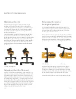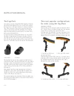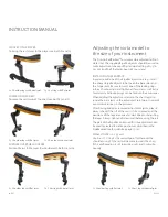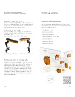
5
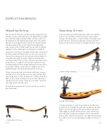
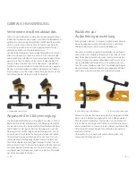
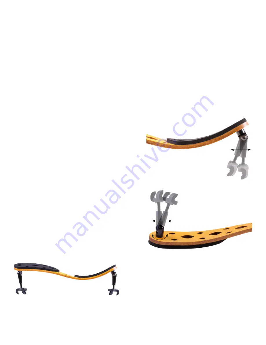
Angle of the shoulder leg
6
Angle of the chest leg
Adjusting the legs
Each leg has a Torx screw connecting the hinge joint with
the base joint and a Torx flange screw connecting the base
joint with the wooden bridge. When the Torx screws are
tightened correctly the locking rings prevent movement
between the hinge joint and the base joint and between
the base joint and the wood. These four locking rings
are essential to the functioning of the rest and should be
replaced if lost or damaged (
6
replacements included).
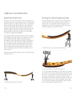
Adjustments to the legs should be made in small increments.
For the maximum stability of the rest it is very important
that the shoulder leg and chest leg meet the instrument at
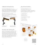
a straight angle when attached. When not attached the
two hinge joints of the rest lean slightly towards each other
(see picture
4
). In order for them to do so and to ensure
the ideal position of the wooden bridge in relation to the
instrument, whatever adjustment is made needs to be
divided between the shoulder leg and the chest leg.
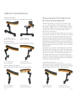
After changing their position, look at both legs sideways
and make sure the adjustment screws of the rubber feet
are parallel to each other (see picture
7
). When placed feet
downwards on a flat surface, all
4
tips of the rubber feet
should touch the surface. If they do not, adjust the tilt of
the hinge joint of the chest leg.
After making adjustments always check all screws have
been tightened.
Narrowing the rest
Increasing the angle of the hinge joint of the shoulder leg
inwards (see picture
5
) will narrow the rest and create a
stronger clamping action. In order to adjust the hinge joint,
loosen the Torx screw enough to allow the joint to move.
Move it to the desired position and tighten the Torx screw.
A similar adjustment needs to be made to the chest leg
(see picture
6
). To make the rest narrower, loosen the Torx
flange screw and slightly rotate the base joint clockwise.
After tightening the Torx flange screw, loosen the hinge
joint. Hold the rest down on a table with the feet parallel
to each other and all four hooks of the rubber feet touching
the surface. Fix the resulting angle by tightening the Torx
screw.
INSTRUCTION MANUAL
10
EN
EN
11
4
Ideal angles of the legs


