background image

Содержание TWIN COMANCHE PA-30

Страница 1: ...AIRPLANE SERVICE MANUAL CARD 1 OF 4 TWIN COMANCHE PIPER AIRCRAFT CORPORATION PART NUMBER 753 645 REVISED OCT 1 1998 1Al Courtesy of Bomar Flying Service www bomar biz...

Страница 2: ...Published by Technical Publications O The New Piper Aircraft Inc 2926 Piper Drive Vero Beach Florida 32960 U S A 2 Member E 3 a GeneralAviation Manufacturers Association...

Страница 3: ...e kept current by revisions distributed periodically These revisions will supersede all previous revisions and will be complete Aerofiche card replacements and shall supersede Aerofiche cards of the s...

Страница 4: ...enerally does not contain hardware callouts for installation Hardware callouts are only indicated where a special application is required To confirm the correct hardware used refer to the PA 30139n i...

Страница 5: ...FUEL SYSTEM X INSTRUMENTS XI ELECTRICAL SYSTEM XI1 ELECTRONICS XI11 HEATING AND VENTILATING SYSTEM XIV ACCESSORIES AND UTILITIES PART U Information Unique to PA 39 1 INTRODUCTION I1 HANDLING AND SERV...

Страница 6: ...l MinimumTurningRadius Servlc ng Landing Gear Struts Service Points Serial Nos 30 1 to 30 852 incl and 30 854 to 30 901 incl Service Points Serial Nos 30 853 30 902to 30 2000 incl Oil Suction Screen O...

Страница 7: ...edals in Neutral Position Determining Neutral Rudder Position Checking Rudder Travel Trim Screw Assembly Flap Control Installati Flap Position Sender Unit Fabricated Aileron Be Fabricated Aileron R gg...

Страница 8: ...er Assembly Bleeding Brakes Brake Cylinder Installation Fabricated Plumb Bob Tool Fabricated Nose Wheel Alignment Jig Fabricated Spanner Wrench Inspection of Rod End Bearings Main Gear Wear Llmts Nose...

Страница 9: ...ling Magneto T m g Marks Engine Tuning Marks Removing Spring From Lead Assembly Assembly Tool Using Assembly Tool Measuring Lead Assembly Length Cutting Metallic Braid From End of Lead Unbrad ng Metal...

Страница 10: ...Regulator Air Gap Checking Voltage Setting Fixed Resistance Method Checking Voltage Setting Variable Resistance Method Adjusting Voltage Regulator Setting Cutout Relay Air Gap Check and Adjustment Cut...

Страница 11: ...30 854 to 30 901 Electrical System Components Serial Nos 30 853 30 902 to 30 2000 PA 39 S N 39 1 NOTE Index for Electrical Schematics may be found in Table XI 111 Grid 3E13 ELT Portable Folding Antenn...

Страница 12: ...ssembly No 751 959 Exploded V ew Combustion Air Blower and Motor Assembly No 753 905 Suggested Set up for Heater Operation Test W ring Connections for Heater Operation Test Heater Fuel Valve Oxygen Sy...

Страница 13: ...Interconnecting Control Cable Installation Checking Stabilator Fnct on Magneto Thing Marks Engine liming Marks Magneto Thing Mark Engine liming Marks Instrument Panel Dome Lights Schematic Instrument...

Страница 14: ...II II Troubleshooting Chart Landing Gear System VU III Main Gear Wear Lirmts VII N Nose Gear Wear L m t s VIII I Propeller Specifications PA 30 VIII U Troubleshooting Chart Engine VIIIA I Propeller Sp...

Страница 15: ...Manual 1 3 Description 1 4 Fuselage 1 5 Wing 1 6 Empennage 1 7 FlightControls 1 8 Landing Gea r 1 9 Brake System 1 10 Engines and Propellers 1 11 Fuel System 1 12 Inst rumencs 1 13 Electronic Equipme...

Страница 16: ...ations described in this manual The description of the airplane included in this section is limited to gencral information Section Il gives leading particulars and principal dimensions while each majo...

Страница 17: ...lane is powered by two Avco Lycoming four cylinder direct drive wet sump horizontally opposed fuel injected engines Tlie propellen are Hartzell full feathering constant speed units controlled by a gov...

Страница 18: ...gine instruments and advance flibt instruments The panel i s shock mounted to minimize vibration to the instruments 1 13 ELECTRONIC EQUIPMENT Rovision for electronic equipment includes varioc s combin...

Страница 19: ...ing 1B23 2 15 Mooring 1C1 2 16 Parking 1C2 2 17 Locking Airplane 1C2 2 18 Towing 1C2 2 19 Taxiing 1C3 2 20 External Power Receptacle 1C4 2 2 1 Operation of Extemal Power Receptacle 1C4 2 22 Cleaning 1...

Страница 20: ...Filters Fuel Systems ServiclngFuel System Filling Fuel Cells Draining Fuel Valves and Lies Dmning Fuel System Electrical System ServlclngElectrical System Oxygen System Servlclngthe Oxygen System Oxyg...

Страница 21: ...PIPER TWIN COMANCHE SERVICEMANUAL THIS PAGE INTENTIONALLY BLANK Revised 1011198 HANDLLNG AND SERVICING...

Страница 22: ...station or buttock line BL and water line WL designations is frequently employed in this manual Refer to Figures 2 3 and 24 Fuselage stations buttock lines and water lines are reference points measur...

Страница 23: ...PIPER TWIN COMANCHE SERVICE hLANUAL Figure 2 1 Three View of l in Comanche P 4 30 Serial Sos 30 1 ro 30 832 inclusive and 30 854 to 30 901 inclus ve HAhDLING AXD SERViCITG Issued I2 3 71...

Страница 24: ...PIPER TWIN COMANCHE SERVICE MANUAL Figure 2 2 Three View of in Comanche P 4 30 Serial Nos 30 853 30 902 to 30 2000 inclusive HANDLING AND SERVICING Issued 12 29 72...

Страница 25: ...d Generator or Alternator Dimensions Height Width Length Oil SAE Number Oil Sump Capacity Oil Consumption Maximum Fuel Aviation Grade Minimum Octane Fuel Injector Bendix Magneto 2 Scintilla Magneto Dr...

Страница 26: ...terand Generator or Alternator Dimensions Height W dth Length Oil SAE Number Oil Sump Capacity Oil Consumption Maximum Fuel Aviation Grade Minimum Octane Fuel Injector Bendix Magneto 2 Scintilla Magne...

Страница 27: ...r Voltage Control Prestolite Vacuum Pump Drive Ratio to Cr lnkshafr Vacuum Pump Drive Rotation Propeller Governor Drive Propeller Governor Ratio Fuel Pump PROPELLER Manufacrurrr Type Hub Blade 2 D a m...

Страница 28: ...ol Restolite Vacuum Pump Drive Ratio to Crankshaft Vacuum Pump Drive Rotation Propeller Governor Drive Propeller Governor Ratio Fuel Pump PROPELLER Manufacturer Type Hub Blade 2 Diameter Diameter Mini...

Страница 29: ...lly retractable Shock Strut Type Combination Air and Oil Fluid Required Struts Brakes MIL H 5606 Red Strut Extension Static Load 2 7 5 in 4axinium A i r Pressure Strut 100 psi Tread Wldth from each ti...

Страница 30: ...h tire center Wheel Base Nose Wheel Travel Main Wheel Toe ln Turning Radius Min Wheel Nose Wheel Main Brake Type Tire Nose Tire Main Tire Pressure 2 BLADE ANGLE AT 30 I N RADIUS 3 SERIAL NOS 3 2 TO 30...

Страница 31: ...Without Vertical Fin WINGS Span Width Chord Station 25 inches Station 62 inches Station 2l l inches Dihednl Leading Edge Incidence Wing Twist Lcngth of Flap Lmgth of Aileron Stabilator Overall Span Fi...

Страница 32: ...AREAS Total Wing Area Including Aileron and Flaps 178 sq ft Aileron 14 1 sq ft Flap 20 2 sq I t Stabilator including trim lab 32 5 sq ft Fin 9 0 sq ft Rudder 5 9 sq ft CONTROL SURFACES TRAVEL I REFER...

Страница 33: ...PIPER TWIN COMANCHE SERVICE MANUAL Figure 2 3 Station Reference Lines Fuselage HANDLlNG A N D SERVICING Issued 12 29 72...

Страница 34: ...PIPER TWlN COMANCHE SERVICE MANUAL HANDLING AND SERVICING Issued 12 29 72...

Страница 35: ...HT ENGINE LEFT GEAR TRIM SENSOR MAJN G 4R PUSH PULL 6 FUEL PUMPS FUEL SELECTOR VALVE CONTROLS CONTROL CABLE TIP TANK FUEL UNE 7 MAIN N E L CELL OUTLET UNE ELECTRICALWIRES 14 AILERON AND FLAP CONTROL P...

Страница 36: ...MECHIHISM 4 MAIN FUEL CELL OUTLET 10 ROTATING BEACON 6 FUSELAGE AFT SECTION INTERIOR 11 STABILATOR BALANCE ARM AND WEIGHT STABILATOR i 6 BRAKE FLUID RESERVOIR CENTRAL AIR FILTER HEATER CONTROL CABLE...

Страница 37: ...KE FLUID RESERVOIR CENTRAL AIR FILTER HEATER NOSE GEAR PARALLELING RELAY 7 BAGGAGE AREA 8 OXYGEN FILLER 9 VERTICAL FIN ATTACHMENT BOLTS ELT TRANSMITTER 10 RUDDER CONTROL HORN STABILATOR TOROUE TUBE ST...

Страница 38: ...9 WING TIP 10 ENGINE CONTROL CABLES ELECTRICAL WIRE CONNECTORS FUEL LlNE CONNECTIONS STATIC AIR LlNE CONNECTIONS BRAKE LlNE CONNECTIONS AND FRONT AND REAR SPAR AllACHMENT POINTS 11 ENGINE OIL DRAIN 12...

Страница 39: ...screws Remove the carpet thus exposing the floor panel attaching screws To enter the aft section of the fuselage remove the lower rear baggage compartment upholstery panel by removing the attaching s...

Страница 40: ...que the fittings in accordance with Table 11 1A I 1 M I I M I M MAXIMUM I M I I M L M MAX1MI M I MIXIMI M MAXIMUM 1 TABLE 11 IA FLARE FITTING T O R Q U E S TORQUE IXCH POUND Added 10 28 82 HANDLING AN...

Страница 41: ...Following is the formula to be used Refer to Figure 2 8a T Torque desired at the part A Basic lever length from center of wrench shank to center of handle or stamped on wrench or listed for that mode...

Страница 42: ...7039 wise spec f ed by the manufacturel If the boll or nut is spec lned to be lubr cated prlor to tlghtenlng the torque range should be reduced 50 5 Use a bolt length longenoughtoprevent beartngloadso...

Страница 43: ...4 Alum Tension AN 365D AN 3 1 0 NAS 1021D Alum Shaa AN 320D AN 364D NAS 1022D Nut olt size 8 36 10 32 114 28 5 16 24 3 8 24 7 1 20 1 2 20 9 16 18 5 8 18 3 4 16 7 8 14 1 14 11 8 12 1 114 12 Toque Limit...

Страница 44: ...PIPER TWIN COMANCHE SERVICE MANUAL TABLE LI 111 DECIMAL CONVERSION CHART HANDLING AND SERVICING I Issued 12 19 77...

Страница 45: ...Walkways of four parts Drvoe nun skid compound and one part black enamel a r e painted on he right wing and I lap The lines of rivets on the walkway a r e covered with non skid paper strips st cured w...

Страница 46: ...prevented 2 12 JACKING The airplane is provided with a jack pad on each main spar just outboard of the engine nacelle and a support position by making use of the tail skid Refer to Figure 2 9 To jack...

Страница 47: ...weighing procedure while the wheels are on scales or while the wheels are on the ground To level the airplane for purposes of weighing or rigging the following procedures may be used a To longitudinal...

Страница 48: ...E SERVICE MANUAL Figure 2 1 1 Leveling Airplane Serial Nos 30 1 to 30 852 incl 30 854 io 30 90i inci Figure 2 12 Leveling Airplane Serial Sos 30 853 30 902 to 30 2000 inclusive HANDLING AXD 5ERVIClLC...

Страница 49: ...side of the airplane or adjusf either jack until the bubble of the level is centered 2 15 MOORING The airplane should be moored to insure its immovability protection and secunty under various weather...

Страница 50: ...akes that are overheated o r during cold weather when accumulated moisture may freeze the brake 2 17 LOCKING AIRPLANE The cabin and baggage doors a r e provided with a key lock The same key can be use...

Страница 51: ...cks a Taxi forward a few feet and apply brakes to determine heir effectiveness b Taxi with propeller set in low pitch high RPM setting c While taxiing make slight rurns to ascertain the effectiveness...

Страница 52: ...ace a strip of tape on the magneto vents to prevent any solvent from entering these units a Place a large pan under the engine to catch waste b With rhe engine cowling removed spray or brush the engin...

Страница 53: ...h the airplane the following procedure may be used NOTE When horing down aircraft avoid directing water in the fuel tank vents drain tubes or around the sealed cover plates and filler cap access openi...

Страница 54: ...y be cleaned by using an approved air type cleaner or foam upholstery cleaner Carefully follow the manufacturer s instructions Avoid soaking or harsh rubbing CAUTION Solvent cleaners require adequate...

Страница 55: ...airplane If the oleo strur oscillates with sllort strokes appro imatelyone inch and the airplane settles to it normdl posirioli wirliin one o r two cycles after i le rocking force is removed tl c oleo...

Страница 56: ...Place a pan under the gear to catch spillage c At the filler plug relieve air pressure from the strut housing chamber by removing the cap from the a i r valve and depressing the valve core d There a...

Страница 57: ...rut to full compression and fill with fluid if needed 6 Reinstall fill plug and tighten e With the airplane raised retract and extend the gear strut several times to ascertain that the strut actuates...

Страница 58: ...ould be filled to rhe lwel marked on reservoir with the fluid specified in Table 11 1 The reservoir located on the left side of the forward cabin bulkhead in the nose section refer to Figure 2 15 o r...

Страница 59: ...L 13 FILLER ENGINE OIL 6 FILLER MAIN OLEO SHOCK STRUT LAND R 14 FILTER ENGINE AIR INTAKE I FILTER VACUUM REGUUTOR 16 TIRE NOSE GEAR 7 FILLER AUXILIbRY FUEL CELL 16 VACUUM SYSTEM CENTRAL AIR FILTER 8 T...

Страница 60: ...ER AUXILIARY FUEL CELL 7 TIRE MAJN G U R LAND R 8 ENGINE OIL SUCTION SCREEN 9 FUEL INJECTOR 10 AIR VALVE PROPELLER 11 FILTER ENGINE OIL 12 FILLER ENGINE OIL 13 FILTER ENGINE AIR INTAKE 14 BAlTERY 15 T...

Страница 61: ...F AIR FILTER a Remove the right side access panel from the engine nacelle to gain access to the air filter box b Turn the three studs and remove the air filter box cover c Lift the air filter from the...

Страница 62: ...ndling gasoline Fill the fuel cells to the bonom of the filler neck with the fuel specified on the placard located on the underside of the filler cover or in Table 11 1 Each main inboard fuel cell hol...

Страница 63: ...rter All electrical wires should be inspected for chafing and bare wires For detailed information on this system refer to Section XI of this manual 2 63 OXYGEN SYSTEM 2 64 SERVICING THE OXYGEN SYSTEM...

Страница 64: ...more supply cylinders cascade storage system it is recommended that the following procedure be used 1 Before opening any valves check the pressure remaining in the airplane s oxygen cylinder If it is...

Страница 65: ...s and must be retired from service after 24 years or 4380 pressurizations whichever occurs first The month and year of the last test is stamped on the cylinder beneath the ICC or DOT identification b...

Страница 66: ...ccess plate from bottom of the engine cowl b Remove oil drain plug from bottom of the engine sump It is recommended the engine be warmed to operating temperature to insure complete draining of the old...

Страница 67: ...n certain that the screen is properly seated tighten the plug If the plug seems tight this will indicate that the screen is not properly seated and must be disassembled and the above procedure repeate...

Страница 68: ...ing abrasion or pressure Evidence of internal engine damage found in the oil filterjustifies further examination to determine the cause c After the element has been replaced tighten the attachingbolt...

Страница 69: ...t oil may result in high oil consumption as the additives in some of these oils can retard the break in of the piston rings and cylinder walls 2 All new or newly overhauled turbocharged engines must b...

Страница 70: ...clean engine oil may be used as a satisfactory substitute b Check the components to be lubricated for evidence of excessive wear and replace them as necessary c Remove all excess lubricants from comp...

Страница 71: ...he grease into the wheel hub c Use extra care when greasing the Hamell propeller hub to avoid blowing the clamp gaskets Remove one grease fining while applying grease to the other fitting 2 80 LUBRICA...

Страница 72: ...PIPER TWIN COMANCHESERVICE MANUAL THIS PAGE INTENTIONALLY BLANK HANDLING AND SERVICING Revised 10IU98...

Страница 73: ...i Seize Compound Fuel MIL T 5544 Anti Seize Graphite Petrolatum Landing Gear Air Valve 6PB Parker Oil MIL G 6032 Lubricating Grease Gasoline and Oil Resistant Pitot and Static TT A 580 JAN A 669 Anti...

Страница 74: ...SCELLANEOUS LINKAGES 4 TRANWlSSlONS SHOULD BE DISASEMBLED CLEANED INSPECTED AND LUBRICATED AT EACH 6 0 0 H W R INTERVAL OR ANNUALLY ACTUATOR SCREW SHOULD BE LUBRICATED AT EACH 100 HOUR INTERVAL OR ANN...

Страница 75: ...ENDBEARING 27 STRUT HOUSINGATTACHMENT BUSHINGS DRAG LlNK PlVOT AND ATTACHMENT BUSHINGS ZB SHIMMY DAWENER ROO END BEARINGAND MOUNT 29 UPPER AND LOWER TORQUE LlNK BUSHINGS I UPPER AND LOWER TOROUE LINK...

Страница 76: ...BPBBTWIN COMANCHE SERVICE MANUAL Figure 2 20 Lubrication Chart Revised 1 31 74 HANDLING AND SERVICING...

Страница 77: ...PIPER TWIN COMANCHE SERVICE MANUAL Figure 2 20 Lubrication Chart cont I Revised 1 31 74 HANDLING AND SERVICING...

Страница 78: ...ISSION HOUSING DISASSEMBLE AND CLEAN WlTH A QUICK DRYING TYPE SOLVENT WHEN REASSEMBLING TRANSMISSIONS FlLL DUKES TRANSMISSION WlTH DUKES NO 4 LUBRICANT OR DURA TRANSMISSION WlTH MIL G 7118 OR MIL G 22...

Страница 79: ...0 037 0 9398 23 64 0 3593 9 1262 13 64 0 2031 5 1594 35 0 110 2 794 64 0 036 0 9144 T 0 358 9 1281 7 0201 5 1054 7 64 0 1093 2 7781 65 0 035 0 899 S 0 346 8 7884 8 0 199 5 0546 36 0 1065 27051 66 0 03...

Страница 80: ...edure for Converting Inches to Millimeters Refer to Table 11 VI A Example Convert 1 5 inches to millimeters I Read down inches column to I inches 2 Read across top inch column to 0 5 3 Read down and a...

Страница 81: ...68 0 F in the column F to the right To convert 20 F to Centigrade find 20 in the center column and read 6 67 C in the C column to the left F C 70 60 50 40 30 20 10 0 10 20 30 40 50 60 70 80 90 100 11...

Страница 82: ...4 478 14 732 14 986 0 6 15 240 15 494 15 748 16 W2 16256 16 510 16 764 17018 17 272 17 526 0 7 17 780 18 034 18 288 18 542 18 796 19 050 19 304 19 558 19812 20066 0 8 20 320 20 574 20 828 21 082 21 33...

Страница 83: ...cont UtiCES AVDP GAL U S DRY GAL U S LIQ IN JOULES Added 10 28 82 HANDLING A N D SERVICING 268 8 0 1556 1 164 4 405 231 0 0 1337 3 785 0 8327 128 2 540 08333 0 000948 0 1376 CU I N CU FT U S GAL LIQ...

Страница 84: ...ES OF HOSE B NONSELF SEALING AROMATIC AND HEAT RESISTANT HOSE RED NWRALS LETTERS AND STRIPE RED NUMERALS AND LETTERS E SELF SEALING AROMATIC RESISTANT HOSE C FLAME AROMATIC AND OIL RESISTANT HOSE HOSE...

Страница 85: ...PIPER TWIN COMANCHE SERVICE MANCAL SMALL CENTER DRILL Figure 2 22 Removal of Cherrylock Rivets Added 10 28 82 1Dl3 HANDLING A N D SERVlClSG...

Страница 86: ...PIPER TWIN COMANCHE SERVICE MANUAL TABLE 11 VII MAXIMUM DISTANCE BETWEEN SUPPORTS FOR FLUID TUBING DISTANCE BETWEEN SUPPORTS IN TUBE O D IN ALUMINUM ALLOY STEEL 1 Added 10128182 HANDLING AND SERVICING...

Страница 87: ...Paragraph Aerofiche Grid No 3 1 Introduction ID16 3 2 Recommended Lubricants ID16 3 3 Inspection Periods 1D16 3 4 Inspection Requirements 1d16 I 3 4a Defin t ons ID16 3 5 Preflight Inspection ID17 3...

Страница 88: ...r Factory Service Department available through Piper Dealers or Distributors I Inspection Must be performed only by licensed mechanics who are qualified on this aircraft using acceptable methods techn...

Страница 89: ...aragraph 3 5 3 5 PREFLIGHT CHECK The airplane must be given a thorough preflight and walk around check The pilot andlor mechanic must include the preflight check as a normal procedu necessary for the...

Страница 90: ...SERVICE MASUAL 3 6 OVERLIMITS INSPECTION I f the airplane has k e n operated so thzt any of its components have exceeded their maximum operanonal limits check vith the appropriate rnanufacmrer ISSPECT...

Страница 91: ...r and crankshaft 10 Overhaul propeller per latest revision of Hanzell Service Letter No 61 B ENGINE GROUP CAUTION GROUND MAGNETO PRIMARY CIRCUIT BEFORE 1 Remove engine cowl 0 2 Clean and check cowling...

Страница 92: ...of spark plugs Clean and adjust gap as required 0 015 to 0 018 or 0 018 to 0 022 per latest revision of Lycoming Service Instruction No 1042 NOTE If fouling of spark plugs ha been apparent rotate bott...

Страница 93: ...fuel pumps engine driven and electric See Note 6 36 Inspect vacuum pumps and lines 37 Overhaul or replace vacuum pumps See Note 6 38 Inspect throttle alternate air mixture and propeller governor contr...

Страница 94: ...Inspect for excess bearing drag or wheel rubbing against I housing Time 500 0 0 0 0 0 0 0 0 0 0 0 0 0 0 0 0 0 0 0 0 0 0 0 0 0 0 0 0 0 0 0 0 0 0 0 0 0 0 0 0 0 0 0 0 0 Inspection 100 0 0 0 0 0 0 0 0 0 1...

Страница 95: ...ct oxygen outlets for defects and corrosion 19 Inspect oxygen system operation and components 20 Reinstall inspection plates and panels Inspection T me hrs 1 Remove inspection plates and panels See No...

Страница 96: ...chment bolts and brackets Nature of Inspection E FUSELAGE AND EMPENNAGE GROUP cont 13 Inspect stabilator fin and rudder surfaces for damage Refer to latest revision of Piper Service Lener No 679 14 In...

Страница 97: ...ering control 3 Inspect wheels for alignmennt 4 Put airplane on jacks 5 Inspect tires for cuts uneven or excessive wear and slippage 6 Remove wheels clean check and repack bearings 1 7 Inspect wheels...

Страница 98: ...ck generator or alternator output 5 Check manifold pressure indications 6 Check operation of brakes and parking brake 7 Check operation of vacuum gauge 8 Check gyros for noise and roughness 9 Check ca...

Страница 99: ...50 hours of engine operation or every four months whichever comes first Should fuel other than the specified octane rating for the power plant be used refer to Lycoming Service Letter No L185A for ad...

Страница 100: ...r occurs first 14 Refer to the latest revision of Piper Service Letter No 851 15 Refer to A D 81 19 04 and to the latest revision of Rayjay Service Letter No 28 16 Refer to Flight Manual Supplement fo...

Страница 101: ...llation of Aileron Flap 4 14 Removal of Flap 4 1 5 lnstallation of Flap Wing 4 17 Removal of Wing 4 18 Installation of Wing Empennage Stabilator 4 21 Removal of Stabilator 4 22 Installation of Stabila...

Страница 102: ...aces 4 48 Checking Stabilator Control Surfaces 4 49 Checking and Balancing Stabilator 4 50 Checking and Balancing Stabilator 4 51 Checking and Balancing Rudder 4 52 Balancing Ailerons Fiberglass Repai...

Страница 103: ...30 853 to 30 901 inclusive baggage compartment access is found on the right side of the t usClage 31 the trailing edge of the wing On airplanes with serial numbers 30 853 30 902 n d up the baggage do...

Страница 104: ...O F WlNG TIP a Remove the screws attaching the wing tip to the wing b Pull the wing tip far enough off to disconnect the navigation light positive and negative wires at the quickdisconnect fitting c...

Страница 105: ...the machine screws and clamps 2 holding the lamp 3 d Pull the lanip forward and remove the electrical leads 4 from r e a r of t5e lamp hen rrnlove the clamp e To dlsassenlble rhe landing light housing...

Страница 106: ...gure 4 2 a After placing the aileron in position install the inboard and outboard hinge bolts Place the spacer washers to allow for best alignment of hinges b Move the aileron through its full travel...

Страница 107: ...PIPER TWIN COMANCHE SERVICE MANUAL Section A A l Issued 12 29 72 Figure 4 2 Aileron and Flap Installation STRUCTURES l E l l...

Страница 108: ...ANCHE SERVICE MANUAL I SKETCH B I Section A A 1 WL511Cll 1M960 416 4 1110 BOLT A M I W A S H E M960 4 6L Y Y T U120365 428C Section A A Figure 4 2 Aileron and Flap Installation cont Issued 12 29 72 ST...

Страница 109: ...assemblies Flaps with nylon flap rollers will not require lubrication c Swing the flap rearward and install the remaining roller assemblies Move the flap through its full uavel to assure that there is...

Страница 110: ...ydraulic lines before removing mark cable and line ends in some idenufying manner and attach a line where applicable to cables before drawing them through the fuselage o r wing g Drain the brake line...

Страница 111: ...olts from spar web plates ac Check to insureall disconnections have been made then pull the wing directly and slowly away from the fuselage 4 18 INSTALLATION O F WING Refer to Figure 4 3 a Prepare the...

Страница 112: ...PIPER TWIN COMANCHE SERVICE MANUAL Issued 12 29 72 STRUCTURES...

Страница 113: ...PIPER TWIN COMANCHE SERVICEMANUAL Issued I2 29 72 1 2 R E 0 SKETCH C SKETCH D J Figure 4 3 Wing lnstalla ion conr 1E17 STRUCTURES...

Страница 114: ...e manifold pressure and vacuum lines at the wing butt v Connect brake line at the wing butt w Connect the main and auxiliary fuel llnes at the wing ha x If tip tanks are installed connect fuel lines a...

Страница 115: ...ube 2 Install bolts ct through stabilator halves and torque tube 3 Install bolt through stabilator r e a r spar fittings 4 Secure bolts with washers and nuts 5 Attach the aft end of the stabilator tri...

Страница 116: ...e m each stabilator half with mating hole in torque tube and inserting lo cating pin P N 25034 00 2 Install bolt in stabilator rear spar fitrings 3 Ream vacant hole in stabilator and torque tube to 0...

Страница 117: ...e rudder seal to the right side trailing edge skin of the vertical fin h Disconnect the rudder from the two remaining hinge brackets in the vertical fin by removing castellated nuts washers and bolts...

Страница 118: ...ge aft section and align the holes in the front attachment plate of the fin with the holes in the front attachment plate on the fuselage Align the holes in the rear mounting bracket of the fin with th...

Страница 119: ...PIPER TWIN COMANCHE SERVICE MANUAL Issued 12129172 Figure 1 4 Empennage Installar on STRUCTURES...

Страница 120: ...PIPER TWIN COMANCHE SERVICE MANUAL I SKETCH E SKETCH F Figure 4 4 Empennage Installation cont Issued 12 29 72 STRUCTURES...

Страница 121: ...Figure 4 5 a Ascertain that new windshield is cut to match windshield removed b Apply Restite Tape No I63 o r equivalent over edge of windshield Apply rwo thicknesses on windshield a t center post c A...

Страница 122: ...PIPER TWIN COMANCHE SERVICE MANUAL CTRICU TAPE R E S m E TAPE FWESmE TAPE 12 THICKNESS PRESTlTE TAPE Figure 4 5 Windshield nscallacion STRCCTCR ES Issued 12 9 72...

Страница 123: ...ble inner and outer window by cementing rubatex strip t o inner window using carbolene neobolene cement C I Leave 0 06 t o 0 I2 gap between ends of rubatex strip to form drain at the lower aft edge of...

Страница 124: ...gnment of the main door latch and the auxiliary latch with their respective latch striker plate If the door fails to align remove it and reposition the two serrated door hinge bushings I Repeat the ab...

Страница 125: ...y 4 43 INSTALLATION AND ADJUSTMENT O F DOOR LOCKING MECHANISM Reitr to Figure 4 8 a Install the upper I and lower 2 latch assemblies with machine screws b Install latch cable assembly 0 and connect th...

Страница 126: ...d position neutral handle position no force applied and both latches are retracted when the handle is in open position full r e a r j Ascertain that the flat portion of the door lock release tube I 2...

Страница 127: ...PIPER TWIN COMANCHE SERVICE MANUAL Figure 4 9 Skin Material and Thickness STRUCTL2ES Issued 12 29 72...

Страница 128: ...PIPER T W l S COMANCHE SERVICE M A N U A L...

Страница 129: ...PIPER TWIN COMANCHE SERVICE MANUAL Issued 12129 72 STRUCTURES...

Страница 130: ...PIPER TWIN COMANCHE SERVICE MANUAL 173UI ACCESS HOLE COVER RATE 17315 KCESS WLE AN 507 8 32R10 Figure 4 10 Typical Access Holes STRUCTURES Issued 1 1 19171...

Страница 131: ...e of any repair work being accomplished on the stabilator the complete stabilator trim tab and trim tab mechanism should be checked for Yree play Refer to Paragraph 4 47 for complete details on checki...

Страница 132: ...few inches above the trim tab trailing edge Place the straightedge next to the trim tab inboard center trailing edge and pasping the tab gently move it up and down mark the h i t s of tab free play on...

Страница 133: ...d or repainted it must be balanced before the irplane is flown b Stabilator inspllation must be complete before balancing including tabs and paint Stabilator control cables 2 and 3 must be disconnecte...

Страница 134: ...force between 2 71 and 2 88 pounds will balance the stabilator with the spring scale hooked to the bolt that fastens the two stabilator connecting tabs arm of 17inches As soon asa master check weight...

Страница 135: ...4 PLATE PIN 2317940 5 BALANCE ARM WEIGHT 6 MASTER CHECK WEIGHT Pm 2 Figure 4 1 1 Balancing Stabilator Serial Nos 30 1 to 30 852 incl 30 854 to 30 901 incl 30 1717 30 1745 to 30 2000 incl Figure 4 1 2...

Страница 136: ...olt which fastem the two stabilator onnecting tabs arm of 17 inches As soon as a master check weight is available the balance should be checked for accuracy e After balancing is accomplished the check...

Страница 137: ...and the scale e Measure the distance in inches between the point at which the support on the scale contacts the rudder surface and the centerline of the rudder hinge This is Measurement D o n Figure...

Страница 138: ...CE MANUAL 1111 SUPPORT KNIFE EDGE BOLTTHRU HINGE RUDDER HINGE CENTER M E A S U R E M E N T D 8ALANCE WEIGHT ACCURATELY BALANCE STAND F gure 4 13 Checkmg and Balanc npRudder INTENTIOKALLY LEFT BLANK ST...

Страница 139: ...or cavity Do not undercut the edge lf the scratch o r caviryis shallow and peneaates only the surface coat COnMue to step h c Pour a small amount of resininto a jar lid o r on a piece of cardboard jus...

Страница 140: ...y ragged edges cur back to sound material c Remove paint rhee inches back from around damaged area d Working inside the saucrure bevel the edges to approximately a 30 degree angle and rough sand the h...

Страница 141: ...squeegee o r broad knife work out all a i r bubblesinthe patch Work from center to edge pressing patch firmly against the structure Allow parch to cure for 15 to 20 minutes m As soon a s the patch be...

Страница 142: ...Solvents Methylethyl Ketone Obtain From Local Suppliers Methvlene Chloride DuPont Company Wilmington Del 19898 Cleaners ABS Solvent Cements Fantastic Spray Perchlorethylene VM P Naphtha Lighter Fluid...

Страница 143: ...PIPER TWIN COMANCHE SERVICE MANUAL 071 Hot Alr Oun Figure 4 14 Surface Scratches Abrasions or Ground in Dirt F gure4 15 Deep Scrarches Shallow N cks and Small Holes Added 10 28 82 STRUCTURES...

Страница 144: ...PIPER TWIN COMANCHE SERVICE MANUAL Figure 4 17 Welding Repair Method Added 10 28 82 STRUCTURES...

Страница 145: ...d is very small it may be quicker to make a satisfactory cement by dissolving thermoplastic material of the same type being repaired in solvent until the desired paste like consistency is achieved 2 T...

Страница 146: ...be repaired by cutting out the damaged area and replacing it with a piece of similar material 3 When cutting away the damaged area under cut the perimeter and maintain a smooth edge The patch and or...

Страница 147: ...Added 10 28 82 Figure 4 19 Various Repairs STRUCTURES...

Страница 148: ...PIPER TWIN COMANCHE SERVICE MANUAL Figure 4 20 Repair of Stress Lines Figure 4 21 Repair of Impacted Damage Added 10128182 STRUCTURES...

Страница 149: ...Lacquer Thinner R7KCI2O Glidden Thinner No 207 b Safety Walk Material Walkway Compound and Matting Nonslip included in Piper Part No 179872 4 60 APPLICATION O F LIQUID SAFETY WALK COMPOUND Liquid safe...

Страница 150: ...SURE SENSITIVE SAFETY WALK Wipe area with aclean dry cloth to insure that no moisture remains on surface Do not apply when surface temperature is below 50 F Apply pressure sensitive safety walk as fol...

Страница 151: ...rim lH3 5 14 Adjustment of Aileron Trim lH3 Stabilator Co trols IH4 5 16 Removal of Stabilator Control Cables IH4 5 17 Installation of Stabilator Control Cables IH5 5 18 Removal of Stabilator Torque T...

Страница 152: ...llation of Rudder Trim Screw and Cable Assembly Forward 5 41 Removal of Rudder Trim Screw and Cable Assembly Aft 5 42 Installation of Rudder Trim Screw and Cable Assembly Aft 5 43 Removal of Rudder Tr...

Страница 153: ...ank 1 1 18 5 56 Removal of Step Lock Assembly 1 1 18 5 57 Installation of Step Lock Assembly 1 1 19 5 58 Rigging and Adjustment of Flaps 1 1 19 5 59 Checking Flap Indicating System 1123 5 60 Rigging a...

Страница 154: ...nd sprocket is fixed on the left control tube which is coupled to the primary aileron control cable The cable is routed under the floor along the side of the fuselage to the main spar and out through...

Страница 155: ...FACE 4 2 1 0 OF INSTRUMENTPANEL 88 25 88 73 L W 2 5 9e 7 88 tJ 2a Neutral position 13 aft vertical Neutral to Fwd 3 51 i n c 6 6p Total Neutral to Aft 3 18 in NOTE 26 lb 20 18 lb 20 CABLE TENSIONS GIV...

Страница 156: ...bilator and Stabilator Trim Tab Rudder Note In neutral position the rudder is rigged lo right of the rudder f i n Cable Tension Aileron Stabilamr Stabilator Trim Tab udder I Rudder Trim I l l MEASUREM...

Страница 157: ...before withdrawing cables through struchueo c Tie a cord to cable end before drawing cable through stmctures to facilitate cable reinstallation d Turnbuckle stations are given at neutral position e Wh...

Страница 158: ...y to allow withdrawal of the sprocket bracket 4 Remove bolts and screw holding the sprocket bracket to the bulkhead 5 Withdraw the square tube assembly NOTE If an Autopilot roll servo is installed in...

Страница 159: ...ontact then withdraw the aft collar until the first of its staggered holes align with the holes in the control tube 4 Install bolts 17 in aft collar 5 Check clearances between either collar and cable...

Страница 160: ...BLOCK CONTROL TUBE I I CONTROL CABLE STABILATOR 31 COLLAR CONTROL SHAFT 12 BOLT NUT ASSEMBLY 14 ADJUSTMENT SCREW 13 CONTROL CHAIN AILERON 35 COVER 14 FITTING ROLLER ATTACHMENT 36 SPROCKET AXLE 15 ROLL...

Страница 161: ...PIPER TWIN COMANCHE SERVICE MANUAL SKETCH E A200 A201 Figurc 5 1 Conlrol Column ln lalli lion conr Revised 4 26 78 SURI CC OS I I5 1G17...

Страница 162: ...Check that there is minimum end play in the bearing tolerance 0 003 to 0 013 of an inch and that the control tuberotates freely through 180 degrees Install safety wire 16 in t e cap bolts 5 In early...

Страница 163: ...IRED WITH A LONG THROAT ONLY CORRECT METHOD Figure 5 la Correct Method of Installing Rod End Be3 ings PIPER TWIN COMANCHE SERVICE MANUAL Added 4 26 78 SURFACECONTROLS DAMAOE UEOL DAMAOE MERE IMPROPER...

Страница 164: ...rom either wing the following procedure may be used I Remove the access plates from the aft underside of the wing at stations 72 0 115 5 and 139 5 and the fairing strip from between the underside of t...

Страница 165: ...n Autopilot roll servo isattached to the balancecable remove theslot head screws from the bridle cable clamps at the center of the fuselage Remove the safety sleeves inboard of each clamp 7 Draw the c...

Страница 166: ...olt washer nut and cotter pin NOTE Do not tighten turnbuckle fork ends on the bellcrank so tight that the end cannot rotate 6 If the forward control cables in the fuselage are installed connect the st...

Страница 167: ...I IS SKETCH CI Revised 1 31 74 Figure 5 2 A l e r o n Control lnstallatlon SURFACE CONTROLS 1G23...

Страница 168: ...LE GUARD AND THE 1 9 3 1 IKETCH PULLEY 15 FWD VIEW A A AILERON RUDDER INTERCONNECTSYSTEM I L E F T RUOOER CABLE 2 LEFT AILERON CABLE 3 CABLE ASSEMBLY 4 RIGHT RUDDER CABLE 5 RIGHT AILERON CABLE 6 CABLE...

Страница 169: ...tension from the control system by rotating one of the turnbuckles attached to the bellcrank 1 or 5 c Disconnect the turnbuckle ends from the forward and aft ends of the bellcrank by moving the cotte...

Страница 170: ...ck and adjust the aileron for neutral position on aircraft without the Airflow Modification Kit installed by the following procedure 1 Place a modified straightedge as shown in Figure 51 against the u...

Страница 171: ...line and establish neutnl or zero on the protractor Remove the control wheel block and adjust the bellcrank stop bolts to the specific aileron travel from neutral s given in Table V l or Table V IA S...

Страница 172: ...baggage area 2 If not previously accomplished mark the upper set of cable ends to facilitate reinstallation and with the trailing edge of the horizontal stabilator in the down position loosen and disc...

Страница 173: ...ll the aft stabilator controlcables that route from the balance arm 30 to fuselage station 172 0 the following procedure may be used 1 Place the ah cables within the fuselage f r o m the right rearacc...

Страница 174: ...the left and right control columns 10 With the cable in the pulley groove install the pulley in the lower bracket at the forward bulk head and beneath the left control column by installing bolt and nu...

Страница 175: ...rudder arm k Remove the components of the torque tubc assembly noting the position of parts for proper reassembly and use the following procedure 1 Remove the left bearing block 40 by tapping with a...

Страница 176: ...PIPER TWIN COMANCHE SERVICE MANUAL I SKETCH 8 i 1 A 2 6 2 I SKETCH C VIEW A A I i SKETCH D F g u r e 3 5 Stabllator and Stabliaror Trlm Controls Issued 12 29 72...

Страница 177: ...20 TUBE l DlC TO I I I C I O R 2 2 M D U M T I M L 8 I I A L I E 1 Y P P E I 2 I DIC TOR W I R E l l M 21 M O Y a I I Y T B I I I C I L T 25 H I H D L F 21 C I A M l I Y P P O l l 27 I T E M C R A M M...

Страница 178: ...forward and the head of the outboard bolt aft Install nuts and washers then torque 6 Install the counter balance arm 30 in the horn and secure with bolt ct and nut 7 Install bearing blocks 40 onthe to...

Страница 179: ...ilator as shown in Figure 5 4 Thistool may be fabricated from dimensions given in Figure 5 19 2 Set on a bubble protractor the number of degm up travel as Sven in Table V I or Table V IA and place it...

Страница 180: ...as measured along the underside of the control column to the wheel 5 Should the neutral position of the control wheel andlor cable tension be incorrect adjust the turnbuckles in tllc aft section of t...

Страница 181: ...e right r e a r family seat if installed and remove the back panel access dour froni the baggage area d Trim cables 2 may be blocked to prevent the unwrapping c j f cables from the u i m drum by remov...

Страница 182: ...the old cable is damaged or cut and the replacement is of undetermined length a For cables of known length the following procedure should be used 1 Draw the cable end forward from the pulley located d...

Страница 183: ...he cable guard bracket from the trim servo drive pulley by removing screws 4 Raise the idler pulley above the fixed cable guards on the right side by removing the pulley bolt 5 Install the pitch trim...

Страница 184: ...rank assembly 34 by removing the cotter pin castellated nut washers and bolt from the bellcrank at the upper end of the control screw station 265 6 h Separate the lower bearing block brace from the br...

Страница 185: ...ure 5 5 a Level the airplane Refer to Leveling Section 11 b Remove tail cone fairing from fuselage by removing the attaching screws c In airplanes with Serial Nos 30 1 to 30 852 inclusive and 30 854 t...

Страница 186: ...ft on the drum Minimum allowable is one and one quarter turns 5 27 REMOVAL O F TRlM INDICATOR AND WIRE Refer to Figure 5 5 a Remove the lower tail cone fairing by removing attaching screws b Remove th...

Страница 187: ...3 and 14 by removing the cotterpin castellated nut washer and bolt d To loosen the two halves of the torque tube 12 remove the two bolts 8 that secure the right inboard pedal 10 to the torque tube e D...

Страница 188: ...RING BLOCK RlGHT 10 RUDDER PEDAL TORQUE ARM RlGHT SlDE INBOARD 11 STEERING ROD RlGHT 12 TORQUE TUBE 13 BEARING BLOCK CENTER 14 IDLER LINK RlGHT 15 RlGHT RUDDER PEDAL TORQUE ARM LEFT SlDE 16 CONNECTING...

Страница 189: ...fork ends of the turnbuckles 22 to the arms of the torque tube assembly with bolts washers and castellated nuts j Rotate the turnbuckle barrels until required tension is reachtd as given in Table V l...

Страница 190: ...heleft cable only over the pulley at station 137 0 under the pulley just aft of the main spar at station 115 0at the forward cablin bulkhead at station 52 0 CAUTION When stringing the cables on the fr...

Страница 191: ...PIPER TWIN COMANCHE SERVICE MANUAL Issued 12129172 Figure 5 10 Rudder and Rudder Trim Connols SURFACE CONTROLS...

Страница 192: ...AILERON CABLE 3 CABLE ASSEMBLY 1 RIGHT RUDDER CABLE 5 RIGHT AILERON CABLE 6 CABLE ASSEMBLY 1 S T A B I M T O R CONTROL CAEILES 8 PULLEY BRACKET _ 9 TURNBUCKLE 10 SPRING II CLAMP I SKETCH C A281 SKETC...

Страница 193: ...acket Disconnect the rudder fmm the two remaining hinge brackets in the vertical fm by removing castellated nuts washen and bolts h Move the rudder to the right or left and upward to sepantc the hinge...

Страница 194: ...trailingedge Refer to Figure 5 12 6 Apply masking tape on 90 to airplane centerline between stabilator halves immediately beneath rod inserted on rudder On tape mark the airplane centerline stabilator...

Страница 195: ...e pencil marks 3 Disconnect the rudder trim system at the lower end of the trim bellcrank at station 251 5 4 With the small rod attached to the trailing edge of the rudder swing the rudder in both dir...

Страница 196: ...nd aft corners of foot recess by removing attaching screws Remove the right family seat if installed and remove the access door from the back panel of the baggage area b Remove the top skin assembly f...

Страница 197: ...rpin d Draw the ends of the cable through the bulkhead hole at mid fuselage near the forward bulkhead then under the pulleys at station 50 0 aft through the bulkhead holes and under the pulleys at the...

Страница 198: ...d a i m drum mounting bracket tu the bulkhead above the trim drum Slide the guide bracket aft on the rube assembly h Free the tube assembly 12 from the aft pornun of the universal joint aft of the n i...

Страница 199: ...Remove spring by removing roll pin from bushing f Separate the bellcrank assembly 34 from its mounting bracket assembly by removing the cotter pin nut washer and bolt 33 from station 251 5 g Disconnec...

Страница 200: ...chtng screws 5 45 RIGGIN3 AND ADJUSTMENT OF RL DDER TRIM COhTROLS Refer to Figure 5 10 a Remove the access panel located on the right side of the fuselage just for ward of the stabilamr b Place the ai...

Страница 201: ...bungee assembly from the trim bellcrank and adjust to bring the rudder to neuaal Maintain 0 375 of an inch thread engagement of rhe rod end bearing in the bungee tube Remove check rod k o m rudder NO...

Страница 202: ...g To install and wrap the trim cable locate the center of the cable meas uring from end to end h Insert the center of the cable into the cable slot in the drum and install the lock pin i Hole the dru...

Страница 203: ...emoving the cotter pin castellated nut and bolt 19 3 Remove the pivot bolt at the top spar support tube 11 by removing the cotter pin nut washer and bolt 4 If not previously removed separate the actua...

Страница 204: ...the rear spar 7 Draw the spar support assembly from its recess in the center fuselage 5 50 CLEANING INSPECTION AND REPAIR O F FLAP TRANSMISSION a Clean the transmission assembly with a suitable solven...

Страница 205: ...anently secure ends with bolts washers castellated nuts and couer pins Allow cable ends freedom to rotate 5 Install the electrical leads to the rnoror and coil assemblies on the for ward right side of...

Страница 206: ...w 28 counterclockwise until the bushing hole in the end of the screw housing aligns withthebottom holes of the actuating arms Install adapter 31 bushing 30 bolt 29 washers and nut 3 Connect the motor...

Страница 207: ...ate from the wheel well and flap bellcrank access plate a t starion 72 0 3 Wirhin the fuselage disconnect the conaol cables 2 and 9 from the actuating arm 17 and 18 a t the rurnbuckle end 20 by removi...

Страница 208: ...fuselage short cable in the aacka of the pulley at the spar support bracket ll install the pulley on the bracket of the support by installing nuts washers and bolts 9 Connect the cable short cable wit...

Страница 209: ...r to Figure 5 15 Removal of the flap bellcrank may be accomplished by the following procedure a Remove the flap bellcrank access plate from the underside of the wing a t station 72 0 and irom the righ...

Страница 210: ...e flap down to the extended position g Place the bellcrankin the extended position and guide the conaol rod through the hole in the aailing edge of the wing h Attach the flap to the aft end of the con...

Страница 211: ...and 30 854 to 30 901 inclusive remove the rear sear In airplanes with Serial Nos 30 853 30 902 and up remove the seats seat tracks carpet and floor panels bemeen the main and rear spar 7 Remove the f...

Страница 212: ...C o r T E P P l N 2 r S E a 2 5 I m I U S U I S I I O U 2 6 P I N 2 7 B I I 1 R E 5 0 L L N O I D 2 8 I P A Y S U I 5 5 I O U 5 C W W 29 M O L T 30 B U I M I H B 31 AD PTEm 32 W U i 3 3 C A B L L C O...

Страница 213: ...PIPER TWIN COMANCHE SERVICE MANUAL Issued 12 29 72 Figure 5 15 Flap Control lns allalion conr SURFACE COKTROLS...

Страница 214: ...o achieve 27 1dqlree of flap deflection The angle of the flap with the airplane level should be 40 1degree c Safety the wnbuckles 7 Adjust the actuating screw of the up limit switch 14 located on the...

Страница 215: ...sender arm against stop 9 the ohmmeter should indicate irom 29 6 to 31 3 ohms If incorrect resistance o r fluctuation is found the sender should be replaced S Check sender ground contact to mounting b...

Страница 216: ...i cator hand on the instrument panel is a t the boccom of the v hire arc c Operate the nap system and heck iur proper operation d Check the turnbuckles and push pull rods for safeties NOTE When deterr...

Страница 217: ...INTENTIONALLY LEFT BLANK...

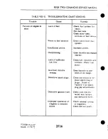
Страница 218: ...tion I Control wheels not synchronized System not lubricated properly Cable tension too high Control column hori zontal chain improperly adjusted Pulleys binding or mbbing Cables nor in place on pulle...

Страница 219: ...ncorrect aileron travel Correct aileron travel cannot be obtained by adjusting bellcrank stops Control wheel stops before control sur faces reach full travel Incorrect rigging of aileron system Ailero...

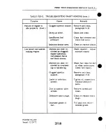
Страница 220: ...tabilator binding at stabilator bearings Cables not in place on pulleys Cables crossed or routed incorrectly Stabilator stop bolts incorrectly adjusted Stabilator cables incorrectly rigged cont Lubric...

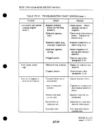
Страница 221: ...lubricated properly Cable tension too high Pulleys binding or rubbing Cables not in place on pl lleys Trim tab hinge binding Cables crossed or routed i icorrectly SYSTEM Adjusl in accordal e with Tabl...

Страница 222: ...ROL SYSTEM Trim indicator not prop erly adjusted Trim indicator wire broken Trim indicator wire broken Broken indicator ten sion spring Forward h pulley dipping when uank is turned System incorrectly...

Страница 223: ...e bear ngblocks in need of lubrication Cable tension too high Pulleys binding or rubbing Cables not in place on pulleys Cables crossed or routed incorrectly Adjust cable tension per Table V l and para...

Страница 224: ...Cause Rudder pedals not neutral wk e rudder is streamlined Incorrect rudder travel RL DDER CONTROL SYSTESI Rudder cables incor rectly riaed Rudder beucrmk stop incorrectly adjusted Nose wheel contacts...

Страница 225: ...Isolate cause and repair v Flaps fail to extend or retract though flap solenoid actuates Me tor circuit Flaps fail to xtend or retract Flap solenoid does not actuate Solenoid circuit FLAP COlrTROL SY...

Страница 226: ...ring Turn switch on Rcset circuit break r Check grcund conncchcjn l rskand repar Repair Flaps have erratic sluggish or retarded operation during ex tension and retr c tion KOindication of flap positio...

Страница 227: ...act Up limit switch in Adjust flap in accordance correctly adjusted with paragraph 5 58 Flaps not synchronized Incorrect rigging Rig in accordance with or fail to fit evenly when retracted 83302 54 on...

Страница 228: ...LS cont a SURFACE CONTROLS Added 1131 74 Trouble Cause Remedy Right flap fails to lock when in the retracted position FLAP CONTROL SYSfEM wnt Flap actuating cable has inruffiaent slack Spring on flap...

Страница 229: ...PIPER TWIN COMANCHE SERVICE MANUAL 15 is MATERIbL 0040 2024 T3 ALUMINUM Figure 5 17 Fabricateci Aileron Bellcrank Rigging Tool Issued 12 29 72 Surface Controls...

Страница 230: ...LENGTH A Ln 4 4 0 421 0 1 7 0 343 om 5nxg n m r oz mP Q r j 4 00 1 I 1 1 1 C 0 50to 1 00A MATERIAL ALUMINUM PLATE SPAR MATERIAL MAY BE USED Figure 5 18 Fabricated Aileron Rigging Tool Issued 12 29 72...

Страница 231: ...MANUAL Figure 5 19 Fabricated Stabilator Rigging Tool V f n I I I I I I I I I f Issued 12 29 72 t 14 I I Surface Controls f I 7 1 f R SERIAL NUMBER 30 1 TO 3Cb1716 INCL 30 1718 TO 30 1744 INCL 30 171...

Страница 232: ...PIPER TWIN COMANCHESERVICEMANUAL GRIDS 1J16 THRU 1524 INTENTIONALLY BLANK SURFACE CONTROLS Revised 101Y98...

Страница 233: ...gs is not positive evidence that broken wires do not exist Figure 27 1A shows a cable with broken wires that were not detected by wiping but were found during a visual inspection The damage became rea...

Страница 234: ...echnique I INDIVIDUAL OUTER WIRES WORN MORE THAN 50 INDIVIDUALOUTER WIRES WORN MORE THAN 40 50 NOTE BLENDING OF WORN AREAS INDIVIDUALOUTER WIRES WORN LESSTHAN 40 WORN AREAS INDIVIDUALLY DISTINGUISHABL...

Страница 235: ...s vapors and liquids can accumulate Note Check all exposed sections of cable for corrosion after a cleaning andlor metal brightening operation has been accomplished in that area e Cable Maintenance Fr...

Страница 236: ...flat spots dirt and paint spray Periodically rotate pulleys which turn through a small arc to provide a new bearing surface for the cable Maintain pulley alignment to prevent the cable from riding on...

Страница 237: ...PIPER TWIN COMANCHESERVICEMANUAL Added 1011198 THIS PAGE INTENTIONALLY BLANK APPENDIX I i...

Страница 238: ...PIPER TWIN COMANCHESERVICEMANUAL GRIDS 1K6 THRU 1L24 INTENTIONALLY BLANK APPENDIX 1 Added 1011198...

Страница 239: ...AIRPLANE SERVICE MANUAL CARD 2 OF 4 TWIN COMANCHE PIPER AIRCRAFT CORPORATION PART NUMBER 753 645 REVISED OCT 1 1998 2A1 Courtesy of Bomar Flying Service www bomar biz...

Страница 240: ...Published by Technical Publications O The New Piper Aircraft Inc 2926 Piper Drive Vero Beach Florida 32960 U S A _ _ s Member General Av at on ManutacturersAssoclatlon GARA...

Страница 241: ...llbe kept current by revisions distributed periodically These rev sionswill supersede all previous revisions and will be complete Aerofiche card replacements and shall supersede Aerofiche cards of rhs...

Страница 242: ...manual generally does not contain hardware callouts for installation Hardware callouts are only indicated where a special application is required To confirm the correct hardware used refer to the PA 3...

Страница 243: ...YSTEM X INSTRUMENTS XI ELECTRICAL SYSTEhl XI1 ELECTRONICS Xlll HEATING AND VENTILATING SYSTEM XIV ACCESSORIES AND UTILITIES PART I1 Information Unique to PA 39 I INTRODUCTION 1 1 HANDLING AND SERVICIN...

Страница 244: ...Brace Link Travel Main Gear Side Brace Bearing Tolerance Main Gear Side Brace Link Tolerance Main Landing Gear Installation Left Adjustment of Main Lan Aligning Main Gear Landing Gear Retraction Syst...

Страница 245: ...Coupling Magneto Timing Marks Engine T m n g Marks Ferrule Searing Tool Removing Spring From Lead Assembly Assembly Tool Using Assembly To Mearuring Lead As Cutting Metallic Braid From End of Lea Unb...

Страница 246: ...Fuel System Installation Turbo Fuel Strainer Assembly Fuel Selector Installation Fuel Selector Valve Control Installation Weldon Rotary Fuel Pump Solenoid Valve Fabricated Fuel Q Instrument Panel Seri...

Страница 247: ...ose Gear Door Assembly 7 15 Cleaning Inspection and Repair of Nose Gear Door Assembly 7 16 Installation of Nose Gear Door Assembly 7 17 Adjustment of Nose Gear Door Assembly 7 18 Main Landing Gear Sys...

Страница 248: ...pair of Retraction Push Pull Conuols 7 40 Installation of Nose Landing Gear Push Pull Control Rod 7 41 Installation of Main Landmg Gear Push Pull Control Cable 7 42 Adjustment of Landing Gear Retracti...

Страница 249: ...embly of Wheel Brake Assembly 7 64 Cleaning Inspection and Repair of Wheel Brake Assembly 7 65 Assembly and Installation o f Wheel Brake Assembly 7 66 Replacement of Wheel Brake Disc 7 67 Removal of B...

Страница 250: ...h located on the left main gear will m t allow the gear m retract until weight off the gear has allowed the strut to extend to within three quarters of an inch of full extension When the manifold pres...

Страница 251: ...bly from the oleo housing 10 cut the safer uire 6 at the top ofthe unil and removethe cap bolts 7 that attach thesteeringarm 28 and a l g n e r g u d e bracket 18 to the top of the oleo cylinder 133 e...

Страница 252: ...s loose or turning in cylinder 6 Orifice plate for hole restriction 7 Fork tube for corrosion scratches nicks dents and misalignment 8 Air balve general condition c Repair of the oleo is limited to sm...

Страница 253: ...i Install wiper strip 47 slide washer 48 into position and secure assembly with s ur ring 49 j Ascertain that bushings are installed in the u p p r and lower torque links 4 and 1 I then install both...

Страница 254: ...INTENTIONALLY LEFT BLANK...

Страница 255: ...6 2 s I T E E I I I W A I M 29 NUT 30 C O T T E I P I N 38 B U I M l W G T S Y l l l l O X 3 1 m U S l M G L 0 1 1 33 D L l O C I L l H D E P 34 O R I F I C E TUBL 35 P I S T O N IULIE 36 0 IlMC P I S...

Страница 256: ...PIPER TWIN COMANCHE SERVICE MANUAL Revised 4 6 8 l LANDING GEAR AND BRAKE SYSTEM 2A18...

Страница 257: ...22 securing the upper left 28 and right 18 drag links to the gear mount Note spacer washers 21 between drag links and mount k Remove cotter pins nuts washers and bolts 9and 20 from the s m t hous ing...

Страница 258: ...mbling any units of the hding gear lubricate bearings bushingr and friction surfaces with the proper lubricant as derribed in the Lubrication Chart Section 11 a lnstall the seering bellcrank and align...

Страница 259: ...h 29 or 43 on its mounring bracket on tie lefr drag links and adjust a s given in paragraph 7 44 e Attach the end bearing of the reaaction push pull rod 25 to the drag link clevis 27 using bolt 26 was...

Страница 260: ...comct adjustment of fomard drag link attachment fittings proceed as follows a Remove the cotter pin nut and washer from the bolt attaching the lower drag links 34 and 35 to the strut housing b To dete...

Страница 261: ...PIPER TWIN COMANCHE SERVICE MANUAL Figure 7 2 Nose Landing Gear Installation Revised 10 6 77 LANDING GEAR AND BRAKE SYSTEM 21 23...

Страница 262: ...PIPER TWIN COMAKCHE SERVICE MAXCAL L PIPER KIT 761 082 Flgure 7 2 Sose Landlng Gear lnsrallat on con Revised I0 6 77 LAhDI G GEAR A D BRAKE I I U 2A24...

Страница 263: ...this ad justment may change and now be the cause of the binding k When proper adjusrment is attained the drag ILnks will lock simul taneously and independently of each other whenthe gear is extended m...

Страница 264: ...in Figure 7 5 and attach a plumb bob to the tool Chis tool may be fabricated from dimensions given I n Figure 7 27 c Anach a plumb bob to the fuselage one half inch to the right from center of the tai...

Страница 265: ...283 INTENTIONALLY LEFT BLANK...

Страница 266: ...gto the rear of the nose wheel atthe axleas shown in Figure 7 6 c Ascertain chat the airplane is laterally level Refer to Leveling Section I 1 d Turn the nose wheel until the center line marked on the...

Страница 267: ...ng 9 bushing 10 and spacer 1 I left side only to its mounting bracket c Remove the four pivot bolts attaching the door hinges 2 to the fuselage d Remove the nose door assembly from the wheel well 7 15...

Страница 268: ...e main gear oleo assembly may be removed and disassembledhom the gear oleo housmg with the gear removed horn or installed on the airplane a Place the airplane on jacks Refer to Jachng Section 11 b Pla...

Страница 269: ...mage 2 Retaining pins for wear and damage 3 Lock rings for cracks burrs etc 4 Cylinder and orifice tube for corrosion scratches nicks and excess wear 3 Orrfice plate for hole restriction 6 Fork tube f...

Страница 270: ...2 88 IN1ENTIONALLY LEFT BLANK...

Страница 271: ...T ssc nL 10 B O L T 1 S I C M I 1 L I I I A i i t I 12 N U T O l l r l C E TUBS 83 S CR 14 B I C I U P l l M 0 DlllrlEL T U B E 1 5 0 1 1 M G O l l F l C r T U B E 10 l l N 6 0 l l l r l C C TUBE 1 7...

Страница 272: ...PlPER TWIN COMANCHE SERVICE MANUAL Revised 4 6 81 LANDING GEAR AND BRAKE SYSTEM 2810...

Страница 273: ...he top of the housing tighten the orifice cube locknut 12 Should it be an impossibility to tighten the locknut due to the orifice tube rotating with the nut withdraw the piston tube assembly from the...

Страница 274: ...e line 33 and c a it to prevent dripping and contamination 3 Remove the acces panel aft of the rear spar by removlng attaching screws 4 Swing the landing gear enough to allow insertion of a bungee too...

Страница 275: ...D ROD END BEARINGS Refer to Figures 7 8c a Side Brace Links To determine the serviceability of these pans requires the inspection of the threads for wear by determining the pitch diameter of the threa...

Страница 276: ...ar Side Brace Link Travel Figure 7 8b Main Gear Side Brace Bearing Tolerance LANDING GEAR AND BRAKES Revised 10lU98 Serviceable Bearing PIN 452 382 22943 00 Thread Size 1 2 20 NF 3 518 18 NF 3 Plug Ga...

Страница 277: ...00 112 20 NF 3 4675 I 4550 20766 01 1 2 20 NF 3 4675 14550 i 24911 00 1 2 20 NF 3 4675 1 4550 22577 00 5 8 18 NF 3 5889 1 5764 25046 00 5 6 18 NF 3 5889 1 5764 I Step 2 Step 3 THREAD RING GAUGE METHOD...

Страница 278: ...ear support flitting and into the rear strut arm using enough shim washers 12 between the rear suppon flitting and the strut arm to diminish end play of the strut housing Shim washers are available in...

Страница 279: ...taching bolt and adjust Refer to paragraph 7 4 6 for adjustment of push DUUcontrol cables r lnstall the assist spring 19 between the strut housing and upper drag link s Extend and retract the main gea...

Страница 280: ...INTENTIONALLY LEFT BLANK...

Страница 281: ......

Страница 282: ...PIPER T W I N C O M A N C H E SERVICE M A S l I A L SKETCH B SKETCH C Issued 12 29 72 F gure 7 9 Maln Land ng Gear lnsralla on Left Icon L A S D I N G GEAR A D B R A K E SYSTEM...

Страница 283: ...angle to the center line of the lower drag link 7 26 ALIGNMENT OF MAIN LANDING GEAR a Place a straight edge no less than twelve feet long across the front of both main landing gear wheels Butt the str...

Страница 284: ...rear the wheel is toed out d To rectify toe in or toe out conditions remove bolt connecting upper and lower torque links and remove or add spacers to move the wheel in desired di rection e Recheck the...

Страница 285: ...RS a Ascertain that there is an all around even clearance between the door and wing panel when the door is in the reuacted position b Adjust by loosening the or lunge screws in the wing panel repositi...

Страница 286: ...lectric motorand aansmission assembly torque rube assembly push pull cables for each main gear and a push pull tube to the nose gear Limit switches a r e installed in the system to shut off the motor...

Страница 287: ...PIPER TWIN COMANCHE SERVICE MANUAL Issued 12 29 72 Figure 7 12 Landing Gear Retraction System LANDING GEAR AND BRAKE SYSTEM 2C1...

Страница 288: ...actuator screw 4 and screw nut 3 c Check the gear release arm 1 and amain that it will map lock in place and w i l l require a load of 6 to 12 pounds applied at the end of the arm to release Adjust by...

Страница 289: ...Panrmission housing with grease per special instruction found on Lubrication Chart in Section I1 of this Service Manual 7 36 INSTALLATION OF RETRACTION TRANSMISSION ASSEMBLY Refer to F 7 14 a Ascerta...

Страница 290: ...DISC 7 TRANSMISSION COVER U T E 19 SPRING TENSION 8 W S M I S S I O N GASKET M MOTOR BRAKE ASSEMBLY 0 SCREW BEMING SERUL NOS 30 6 8 AND UP AND USED 10 COUPUNG WTH SERUL NOS 30 1 TO IO BUI 11 BEARING R...

Страница 291: ...Refer to Jackmg Section 11 b Open the reaaction aansmission door and disconnect the aansmission by pulling up on the release lever c Reaact the landing gear until it hangs in the neutral position by u...

Страница 292: ...I Freedom of movement through the housing 2 Corrosion of cable and housing 3 Excess wear of cable and housing 4 Bends and cracks of cable threaded ends d Repair of the push pull controls to limited to...

Страница 293: ...n the left gear cable 2 g Place the adjuaing washer 35 and nut 34 on the cable at the drag link end and install jam nut and end bearing h Attach the cables to the drw Linkr with bolts washers and nuts...

Страница 294: ...n then screw down an additional 0 187 of an inch and secure with jam nut 40 c The round switch used on aircraft without the adjusting rod and arm is ad justed bv compressing the strut until 5 5 inches...

Страница 295: ...forward of the castellated nut A spanner wrench may be fabricated to tighten the castellated nuts see Figure 7 29 NOTE The main gear push pull cables cross each other aft of the retraction transmissi...

Страница 296: ...ERGENn 21 R SMISSION n u n SPRING PA SERIAL NOS m 2 w a 8 1 TVPICAL SAFETY WIRE INSTALLATION 13 TRL31SMlSSlONRElRACl SPRING PA 30 SERIAL NOS 4 3 bND UP 24 B R M ASSEMBLY 15 M O T m SUPPORT ROO 16 TWJI...

Страница 297: ...th the bole inthe clevis then turn the rod end in one complete turn For proper clearance of the clevis in stall the clevis bolt with the countersunk poraon at the left or outboard side I NOTE With the...

Страница 298: ...found necessary to adjust the nose gear rrmuv or add sh rns at the drag link clevis then readjust the push pull rod f Check nose gear and main gear door adjusunent Refer to Paragaphs 7 17 and 7 30 7 4...

Страница 299: ...t on the torque wrench completely retracting the gear i Observe torque reading when the amber gear up indicator light initially comes on The torque reading should not exceed l mits given in Table VII...

Страница 300: ...CH WITH CEHTEI1 UWE W RtfRACTICU TQOUE TUBE a I I C I 01 GRIP AREA 01 U m L E UV01 CaYT DEPC DIffi ON TYPE CF WREMCH EFFECTIVE ADAPTER iII I In PULL RW i i Figure 7 16 Torque Wrench and Adapter Insral...

Страница 301: ...retracuon transmission by pulling up on the emergency release le er Z The dotrn safer lock should be adjusted as close t o the spacer I on the torque arm thru boll 2 a s possible yet freely engage wh...

Страница 302: ...S G SWITCH 7 52 R E M O V A L O F L A S D I Z G GEAR U ARNISG SWITCH a Remole the left s de panel from the throttle quadrant by loosen ng the snap fasteners or rerno Ing attach ng screus b Remove scr...

Страница 303: ...own and locked h Remove the airplane from the jacks i Flight test the airplane to insure proper operation ofthe gear warning system with the gear up and power reduced belou 12 inches of manifold press...

Страница 304: ...or wear and pitting and relubricate i Replace any wheel casting having visible cracks 7 56 4SSEblBLY AND INSTALLATION OF NOSE WHEEL a Ascerrain that the bearing cup 3 in each wheel half is properlv 1n...

Страница 305: ...rod and axle plugs 2 Insert a 1 875 inch diameter rube into the fork and tap out the axle irom the heel amembl 7 In5ert a pr Ing roo1 bet eenrhesideoltheforkassembl and uheeland appl enougil prr urr...

Страница 306: ...ating the tire and removing the snay rings 10 securing the grease seals 6 and seal retainers 5 4 Remove the bearing cones 4 and remove the bolts 7 securing the wheel lalves 5 The bearing cups 3 should...

Страница 307: ...e nut and install dust cover g Install the brake assembly b positioning the brake lining back plates between the wheel and brake disc and the brake cxlinder o n the torque plate Insert the spacer bloc...

Страница 308: ...single groove or isolated grooves up to 0 031 of an inch deep would not necssitale replacement but a grooving of the entire surface would reduce lining life and necessitate replacement of the lining...

Страница 309: ...NDER BODY ANCHORBOLT HOLDING FIXTURE STEP A CYLINDER BODY ANCHOR BOLT HOLDING HOLDING FIXTURE FIXTURE STEP B STEP C CYLINDER BODY HOLDING FIXTURE STEP D F pure7 a Removal and lnstallarion of Anchor Bo...

Страница 310: ...ke cylinder housing g Bleed the bnke system as described in paragraph 7 72 NOTE Replacement brake bingi should be conditioned Perform three consecutive hard braking applications from 45 to 50 mph Do n...

Страница 311: ...PIPER T W I N COMANCHE SERVICE MANUAL I Figure 7 2 4 Brake Systeni Installation LANDING G E A R AND BRAKE SYSTEhl 2D1...

Страница 312: ...the nut 24 washer 23 spring 22 bushing 21 and 0 ring 20 attaching the parking brake arm 25 to the cylinder housing 15 d Remove the lower fluid line fitting 19 and pull out the spring Is 0 rhg 17 and...

Страница 313: ...PIPER W I N COMANCHE SERVICE M S C A L Figure 7 25 Brake laster Cylinder ssernbly L SDIXG GEPlR AXDBRAKE S iSTEll...

Страница 314: ...e cable housing to the upper part of the cylinder asumbly d Connect the brake fluid Lines to the cvlinder fittinps e Bleed the brake system per instructi0 s given in pkgraph 7 71 7 71 BLEEDING PROCEDU...

Страница 315: ...ANCHE SERVICE MANUAL Figure 7 26 Bleeding Brakes s a y I s T Y S I I I U W U O I I D S244a5 3 2 i a 1 r 6 IU I C I 1 U S l i G Figure 7 26a Brake Cylinder Installation L hDISG G L R 4hD BRAKE SYSTEM l...

Страница 316: ...circuit breaker open Wire broken on safety switch Transmission motor assembly hoper ative Transmission motor assembly burned out Micro switches on thrortles out of adjustment Nose gear down limit swi...

Страница 317: ...cuit breaker Trouble Amber GEAR UP light out cont W a r q horn fails ro stop when throttles a r e closed and landing gear is extended Transmlsslon motor assemblv does not shut oii when gear is in full...

Страница 318: ...ns srauonary Landing gear will re cract with oleo s u u t in a depressed con dition Cause Bearing retainer sleeve hits pin Bearing retainer sleeve hits ocher restriction Safety switch out of adjustmen...

Страница 319: ...PIPER TWIN COMANCHE SERVICE MANUAL I I I FRONT I I I I...

Страница 320: ...PIPER TWIN COMANCHE SERVICE MANUAL Figure 7 2 6 Fabricated Nose Wheel Alignment Jig Issued 12 29 72 LANDING GEAR AND B R A K E SYSTEIvI 2D10...

Страница 321: ...I MATERIAL STEEL 4130 125 X 75 X 5 W I I v U 1 MATERIAL TUBE STEEL 41 30 1 3 16 0 3 X 937 1 0 X 1 43 L NOTE AFTER FABRICATION OF ASSEMBLY HEAT TREAT T O 160000 I80000 PSI A104 TVPICAL INCTALL4T13hi I...

Страница 322: ...PIPER TWIN COhlAVCHE SERVICE MANUAL DIAL INDICATOR I I Figure 7 30 Inspection of Rod End Bearings LAKDISG GEAR AND BRAKE SYSTESt Added 6 28 76 2 D 1 2...

Страница 323: ...aragmph 7 23 and Figure 7 8a g Install the downlock spring on the nose gar If only one spring is used obtain Piper Senice Kit COT additional spring installation Refer to Paragraph 7 11 for installatio...

Страница 324: ...PIPER TWIN COMANCHE SERVICE MANUAL F i w 7 31 hiain G a r Wear Limits Revised 41618I LANDING G E M AND BRAKE SYST 2D14...

Страница 325: ...1 1 25046 20768 22577 3412 22943 8330240 Mfg I D 375 373 374 376 4365 4385 4365 4385 49al s00 5611 563 498 500 56 11 563 25 11 249 3731 375 4365 4385 4365 4385 4365 4385 Spring i s extends the measure...

Страница 326: ......

Страница 327: ...t Bushing Bushing w g Bolt Bushing Bushing Bushing Bushing Nose Spring Mfg I D 3745 3755 3745 3755 374 376 37451 3755 3745 3755 3745 3755 3741 376 SOlS SOOO 5015 5000 4995 5005 49951 5005 Spring is ex...

Страница 328: ...de Angle and Stop 8 13 Blade Track Propeller Governor 8 15 Removal of Propeller Governor 8 16 lnstallat onof Propeller Gobernor 8 15 Adjustment of Propeller Governor Engine 8 19 Removal of Engine 8 20...

Страница 329: ...Magneto 2E23 842 Inspection of Magnetos 2EZ 1 8 43 Removal of Magneto 2F2 8 44 Timing Procedure Internal Timing 2F2 8 45 Installation and Timing Rocedure 2F3 I 8 4 6 Harness Assembly 2F5 8 4 7 Inspect...

Страница 330: ...opeller shaft at various pressures Oil pressure from the governor moves the blades into low pitch high RPM The centrifugal misting moment of the blades also tends o move the blades into low pitch Oppo...

Страница 331: ...power plant a To insure proper reinstallation and or assembly tag and mark all pans clips and brackets as to their location prior to the rremo al and o r disassembly b During removal of Larious tubes...

Страница 332: ...ings which will ensure identification during ordinar handling storage and final assembly of part 8 3 TROUBLESHOOTIUG Troubles peculiar to the power plant are listed in Table VIII I1 in the back ol thi...

Страница 333: ...ASTENER 8 RIGHT NOSE COWL 12 DRAIN FllTlNG 13 LEFT SlDE COWL TOP OIL I 1 ADJUST HOUSING TO ACT AS STOP LMD WHEN COWL FLAP IS OPEN 2 IN AT HOU TRAILING EDGE OF COWL FLAP i CONTROL ICOWL AD LIST YNUGETO...

Страница 334: ...the top cowl and secure with anaching screws e Connect the cowl flap control rods to cowl flap with attaching pin washer n d sorter pin f Position the side access panels and secure with fasteners 8 7a...

Страница 335: ...wit11 the engne operating by ilsc of the propeller control on the throttle quadrant CAUTION Prior to errormine any work on the propeller ascertain that 11 m m s r s w t c i and magneto switches are OF...

Страница 336: ...uts are frozen to the studs witl loct re and secured with roll pins so the studs should turn with the nuts Pull the ropell r irnm tlie ngine shaft d In the event that the spinner and spinncr bulkhead...

Страница 337: ...fer to Figure 8 3 for propeller blade are h Check condition of propeller mounting nuts and studs NOTE It is recommended that for s c v m damage internal repain and replacement of parts the propeller s...

Страница 338: ...master switch and magncto switches are OFF grounded and the mixture control is in the IDLE CUT OFF position Clean the nropeller flange starter ring and crankshaft flange b Inst lls iinnerbulkhead 13 o...

Страница 339: ...tripe refer to NOTE under Panmaph 8 9 Screw each stud into t s mating engine flange bushing a few threads at a tune until all are trght Toque the studs to the specifications given in Table V111 I h Sa...

Страница 340: ...manual for an exact pressure ior tllc riisting temperature It is most important that an accurate charge be nialntalned k The amount of air pressure per existing temperature as shown b Txble VIII I I...

Страница 341: ...iption Required Torque Limits Dry Spinner Bulkhead Aft 22 foot pounds Propeller Mounting Bolts 50 foot pounds Propeller Mounting Studs 40 42 foot pounds Spinner Bulkhead Check 3 5 4 0 foot pounds Nut...

Страница 342: ...llrr is suspected t o be wmne it should be referred back to thr Hanzell factow or Certified repair shop a Procedure for obtaining blade angle and adjusting low pitch stop 1 The blade angle refer to Ta...

Страница 343: ...c Propellen having excessive difference in blade track should be removed and inspected for bent blades or for parts of sheared 0 nng or foreign particles which have lodged between hub and c r a n k h...

Страница 344: ...ckwise directionto increase engine speed LER GOVERSOR a Cleanthe mounting pad thoroughly rnalang very certain that there are no foreign parncles in the recess around the drive shaft b Place the govern...

Страница 345: ...8 19 REMOVAL OF ENGINE Refer to Figure 84 The removal of either engine is basicallv the same procedure though tlie routing of some wires cables and lines do v a n between engines Each line should be i...

Страница 346: ...k the engine for any attachments remaning to obstruct its removal v Swing the engine clear and place on a suitable support 8 20 IXSTALUTION OF ENGINE The iinstallarion of either engine is basic ally r...

Страница 347: ...per paragraph 8 7 T o prevent possible high speed bearing failuredue to lack of lubrication during the initla1 start refer to the latest revision of Lycomlng Service Instructions No 1241 w Perform an...

Страница 348: ...LLTER a Place the air filter in the filter box b Position the cover on the box and secure with three stud fasteners c Position the side access panel on the engine nacelle and secure with fas teners 8...

Страница 349: ...EXHAUST STACK 5 BAFFLE RIGHT REAR 22 BAFFLE LEFT REAR 6 SPARK PLUG 23 OIL COOLER 7 LIFTING STRAP 24 EXHAUST STACK 8 FUEL DISTRIBUTOR VALVE 25 EXHAUST STACK HANGER 9 INTAKE AIR DUCT 26 HANGER MOUNTING...

Страница 350: ...PIPER TWIN C O M A N C H E SEIlVICE M A N U A I I SKETCH A Figure 8 5 Engine Installation cont 2E16...

Страница 351: ...ve odor similar to varnish and causes rapid deterioration of synthetic rubber parts and also forms a gummy deposit on the internal metal pans Tlus condtioq however does not occur during normaloperatio...

Страница 352: ...until oil is discharged from the outlet c Replace fuel inlet shipping plug CAUTION DJm t exceed the a b v e air pressures asinternal dam age to the injector may result d After filling with preservativ...

Страница 353: ...PIPER TWIN COMANCHE SERVICE MANUAL 118 INCH 0 D STAINLESS STEEL LINE I I I SF I NOZZLE I I ONE PER CYLINDER1 Figure 8 6 Schemar cD agram of RSA Fuel Injector System Issued 12 29 72 POWER PLANT 2E19...

Страница 354: ...t and injector to engine with nuts and pal locknuts b Secure inlet air plenum to injector with cap bolts and safety c Connect the fuel lines to injector unit d Connect throttle and mixture control cab...

Страница 355: ...peed has been stabilized move the soc pit mlxrure conrrol lever w rh a smooth steady pull toward the Idle CutOif position and o b u n rlic tachornetcr fcr any clianne during the leaning process Cautio...

Страница 356: ...pmgmph 8 38 8 38 CLEANING AKD INSPECTION OF FUEL AIR BLEED NOZZLE a Clean the nozzle with acetone or equivalent and blow out all foreign particles with compressed air in the direction opposite that o...

Страница 357: ...SURROUNOING SURFACE 8 4 3 INSPErnION OF MAGNETOS At time of engine inspection or when a magneto has been removed from the engine the following checks may be performed a Inspect distributor block cont...

Страница 358: ...ed contact surfaces have a dull gray sand blasted almost rough o r frosted appearance over the area where electrical contact is made This means that points a r e worn in and mated to each other thereb...

Страница 359: ...f body and flyweights m Check that the impulse coupling 5yweigfit axle rivers are tight and there a r e no cracks in body n Look at h e lead conduits A few broken strands won t hurc h t if the in sula...

Страница 360: ...etodnve byroraung drive coupling in a left hand direction until the red o r white chamfered tooth on the disaibutor gear appears through the timing inspecuon hole At the same lo c a r i o the drive sh...

Страница 361: ...ck of the starter gear and rhe crankcase parung flange a r e aligned or the m a r k on the front of the starter rmg gear and the drilled hole inthe starter housing align Refer to Figure 8 13 c Rotate...

Страница 362: ...drilled hole in the starter a s shown in Figure 8 13 or the urning mark on the back of the ring gear ahgns wlth the crankcase parting surface Ar this point the light sbould go out k If the lighc does...

Страница 363: ...TAKK Model 86 or 86A or an equivalent direct current high voltage tester capahle of delivering a test potennal of 10 000 volts Connect ground lead of high voltage tester to outer shielding braid of a...

Страница 364: ...insulating sleeve and spring retainer assembly as shown in Figure 8 16 Screw the cable terminal into the tool c Work insulating sleeve and spring retainer assembly into posinon over the cahle and uns...

Страница 365: ...ure 8 16 Using Assembly Tool L REOUIRED LENGTH Figure 8 17 Measuring Lead Assembly Length 5 To determine what length the new lead assembly should be cut to pro ceed as iollows a Measure the length o i...

Страница 366: ...er stamp to correspond i itli correct cylinder number 5 Starting at spark plug location thread new cable thru grommers and ilamps as necessary for correct rourlng of cur end of cable to magneto locati...

Страница 367: ...d of new lead through hole in outlet piace Remove eleculcal tape from lead and install tapered end of ferrule under the bra ded strands of shleiding Form strands of shielding evenly around tapered fer...

Страница 368: ...24 SLde grommet down needle until it seats aghrly against the tapered ferrule 14 Cut wire 3 8 inch from top of grommet outlet See Flgure 8 24 Double wlre over as shown in 4 of Flgure 8 26 Slide eyelet...

Страница 369: ...lamps and cableties as necessary to secure lead to the engine 8 50 INSTALLATION OF HARNESS Before installing harness on magneto check mating surfaces for cleanliness Spray entire fareof grommet with a...

Страница 370: ...insulator b Remove the spark plug from the engine In the course of engine operatio carbon and other comhsnon products will be deposited on the end of the spark plug and will peneuate the lower threads...

Страница 371: ...g Break the spark plug loose with a wrench h warm cylinder head at the time the carbon dioxide is applied will aid in the removal of an excessively seized plug e D o not allow foreign objects t o ente...

Страница 372: ...e is to maintain engine oil pressure within specified limits 60 psi min to 90 psi max Ths valve is not adjustable however the pressure can be con trolled by che addition of a maximum of three STD 425...

Страница 373: ...adjusnng screw out to decrease pressure and in to increase pressure Depending on nstalladon the adjusMg screw may have only a screwdriver slot and is turned with a screw driver or may have the screwdr...

Страница 374: ...em for leaks Fill fuel rank Clean dirty lines screens o r fuel valve Drain watcr from fuel system Increase prime Open thrortle and engage starter Clean fuel strainers and screens Check fuel pump Open...

Страница 375: ...paragraph Y 35 Refer to paragraph 6 35 Tighten all connecrions in the induction sys tem Replace any parts that are defec tive Check cylinder com pression Check entire ignition system Regap spark plug...

Страница 376: ...l connections Replace defecnve parts Remove screen and clean Clean or replace spark plugs Fill ran with recnm mended grade Trouble Failure of engine to idle properly cont Low power and uneven running...

Страница 377: ...ust rhrorrle lever Trouble Low power and uneven running engine cont Flow meter reads high Failure of e n n e to develop full power Tighten all connections and replace defecuve parts Injector must be r...

Страница 378: ...engine mounts Unbalanced propeiler Bent propeller blades Defecnve mounrlng Lead deposit on spark plug Ualfunccioningengine Insufficient oil Dirty oil screens Remedy Adjust governor Adjust propeller l...

Страница 379: ...c r e e n Overhaul Check a i r inlet and outlet deformation o r obstruction Fill oil sump to proper level Remove and clean oil screens Remove and clean oi cooler Trouble Low oil pressure cont High oil...

Страница 380: ...ire englne Check sump for metal parncles and if iound overhaul of engne is indica ced Install new rings Inscall new rings Check e w e carefully for leaking gaskets 0 rings o r sand holes Trouble H gh...

Страница 381: ...l oil consumption stabilizes Replace with oil con forming to specifi cations High and low pressure readings due to ex tremely cold weather a r e not necessarily a malfuncnon Small and long oil lines w...

Страница 382: ...2 F24 INTENTIONALLY LEFT BLANK...

Страница 383: ...er Governor 8A 15 Removal of Propeller Governor KA 16 lnstallat onof Propeller Governor 8A I7 Adjustmenl of Propeller Governor Engine 8 4 19 Removal of Engine 8 2 0 Installat onof E n g n s b 4 20a Pr...

Страница 384: ...r Blad Nozzles 2HII 8 A 4 Ignition System Maintenance 2HI2 8A45 Mapeto 2H I 8 A 4 Inspection of Magneto 2HIZ 8A47 Removal of Magneto 2H15 8A48 TimingF roudure Internal Timing 2H15 8A49 Installation an...

Страница 385: ...11 operated manuall ihrough mechan c I IinLspe Propeller are H a r r x l l lull ieathering con tant speed each controlled b a go ernor mounted on rhe engine pplytng oil through rhe propeller halt21 ia...

Страница 386: ...ict the oil now to the cooler an oil cooler by pass valve is provided to pass the oil directl from the oil pump to the 011pressure filter The oil pressure ftlter screen or element located on the acces...

Страница 387: ...P I P E R T W I N C O M A N C H E S E R V I C E M A N U A L Rcviscd 4 Sl Figure XA I Enginc Cowling and C o r lFlap Rlgglng...

Страница 388: ...removed by pulling out the upper and lower hmge ptns and splitting rhe cowl 8A 6 CLEANING INSPECTION AhD REPAIR OF ENGINE COWLING a The cowling should be cleaned with a suitable solvent and then wipe...

Страница 389: ...ackun kit installed identified bv a letter S in thc dash number NOTE Winen removing the propeller it is unnecessary to remove rhe sninner feat ler the blades or remove tlie air charge When the pro ell...

Страница 390: ...lered on the ground i t should be done w t tlir c l91e onenring by use of the propeller control on tlic tl rottl quadr nt CAUTION Prior to performing any work on the jroneller 3scerr lln tllat 111 mas...

Страница 391: ...rming any work around propeller discharge the dome pressure first a Chesh for oil and grease leaks b Clem the spinner pro eller hub and blades with a non corrosive solvent c Inspect the hub pans for c...

Страница 392: ...ge internal repairs and replacement of parts the propeller should be referred to the Hanzell Factory or Certified Repair Station i Each blade face should be sanded lightly with fine sandpaper and pain...

Страница 393: ...ome air pressure or to insure complete release of all ai pressure place the propeller CONTROL in the feather detent before measuring or releasing propeller air pressure This procedure will insure the...

Страница 394: ...iption Rcquired Torque Limits D V I Spinner Bulkhead Aft 22 foot pound Propeller Mounting Bolts 50 foot pounds Propeller Mounting Studs 40 42 foot pounds Spinner Bulkhead Check 3 5 4 0 foot pounds Nut...

Страница 395: ...bed the procedure given below is used for obtaining blade angle but applies only to the propeller without the spring k t A 227 7 installed There is no way to check the lou pitch blade angle of the pro...

Страница 396: ...ive difference in blade track more than 0 062 inch mav be an indication of bent blades or improper propeller installation Check blade track as follows a With the engine shut down and blades vertical s...

Страница 397: ...ws from clamp e Remove nut and washer from governor adapter mounting stud allowing the control cable bracket to be removed f Remove the governor mounting stud nuts It will be necessarq to move the gov...

Страница 398: ...2 676 INTENTIONALLY LEFT BLANK...

Страница 399: ...2 617 INTENTIONALLY LEFT BLANK...

Страница 400: ...ines on the governor shaft with the engjne drive and rllr cdblc bracket with the governor adapter mountlng stud and slide the governor into position c Vith the governor in position raise it enoug to i...

Страница 401: ...RPM 3 After adjustment is made secure adjusting screw with jam nut 4 With the high RPM adjustment complete the conaol system should be adjusted so that the governor conaol arm will contact the high R...

Страница 402: ...r hose from the breather t u b e atrached to the fire wall and disconnect the turbo oil line from the engine a t the accessory housing n Disconnect the magneto P leads from the magnetos o Disconnect t...

Страница 403: ...o b in the cockpit is full in there will be approximately one eighth inch clearance between the control arm and the door hinge arms h Connect the turbo oil line to the firting at the bonom of the tur...

Страница 404: ...2 622 INTENTIONALLY LEFT BLANK...

Страница 405: ...T 6 OIL FILLER 20 EXHAUST WASTE GATE ASSEMBLY 7 FUEL DISTRIBUTOR VALVE 21 TURBOCHARGER COMPRESSOR SECTION 8 INJECTOR NOZZLE FUEL LINE 22 COMPRESSOR AIR DUCT 9 SPARK PLUG LEAD 23 COMPRESSOR DISCHARGE C...

Страница 406: ...CHE SERVICE MANUAL C241 34 35 1 29 30 31 32 33 29 NUT 30 SPACER 31 SHOCK MOUNT SILVER 32 SHOCK MOUNT GOLD 33 WASHER 34 BOLT 35 SPACER 29 30 32 31 33 34 35 SKETCH A Revised 416 8 1 Figure 8A 5 Engine I...

Страница 407: ...S Refer to Figure 6 for the proper arrangement ofthe engine shock mount ai emblies The topshocksareassembled sothegold colored shock IS aft and the s l i e r colored shock is for ard The louer shock...

Страница 408: ...he bellous re positions the bleed valve causing a change in quantlt of bleed oil which changes oil pressure to the wastegate piston NOTE The density controller is designed to keep the air denbit const...

Страница 409: ...pressure hes tateI to 3 seconds and continue advancing to full throttle slou and ea T h s uill e l m n a t e an overshoot due to turbocharger inertia Th15ih 3 rerm used in conjunction u t h turbo mac...

Страница 410: ...PIPER TWIN COMANCHE SERVICE MANUAL Figure 8A 6 Schematic Diagram of Turbocharged System Issued 12 29 2 POWER PLANT 2H4...

Страница 411: ...of ths turbo unit and secure with clamps c Align the turbo inside mounting lug with the mounting bracket attached to the lower left engine mount and secure with bolt washer and nut d Secure the top o...

Страница 412: ...e control knob in the cockpit is full in the cable is adjusted to allow approximately one eighth inch between the actuating arm and the door hinge arms when full closed 8A 32 FUEL INJECTOR 8A 33 FUEL...

Страница 413: ...Remove the pal locknuts and nuts securing the injector to rhe engine g Pull the a i r plenum back to allow the injector unit to be removed 6 A 36 PREPARATION FOR STORAGE Any unit taken out of service...

Страница 414: ...FUEL N L E T FLOW DIVIDER VALVE TO TURBO CONNECTED TO DECK PRESSURE THROTTLE LEVER LINKAGE CONSTANT HEAD IDLE SPRING CONSTANT EFFORT IMPACT TUBE Figure 8A 7 Schematic Diagram of RSA Fuel Injector Syst...

Страница 415: ...the impact tubes or the annular groove around the venturi For this reason a protective plate should be installed on the scoop mounting flange when performing routing maintenance on the en ne such as...

Страница 416: ...the succeeding steps readjust the idle speed to the desired RPM NOTE The idle mixture must be adjusted with the fuel boost pump OK d When the idling speed has been stabilized move the cockpit mixture...

Страница 417: ...e nozzle as given ir paragraph 8A 42 8A 42 CLEANING AND IKSPECTION O F FUEL AIR BLEED NOZZLE a Clean the nozzle with acetone or equivalent and blow out all fore gnparticles w t h compressed air in the...

Страница 418: ...rounded before working on the engine 8A46 INSPECTION OF MAGNETO At the time of engine inspection or when a magneto h a been removed from the engine the following checks may be performed a Inspect dist...

Страница 419: ...ties or roughness of point surfaces are not harmful Refer to Figure 8A 10 center Neither are small pits or mounts if not too pronounced If there is a possibility of pit becoming deep enough to penetra...

Страница 420: ...coupllng should be replaced Refer to Figure 8A 12 1 Check impulse coupling for excess wear on the contact edges of body and flyweights m Check that the impulse coupling flyweight axle rivets a r e ti...

Страница 421: ...ring the magneto to the encne acces sory housing e Pull the magneto from the engine POWER PL 4XT Issued 11 1917 SA 4 6 TLbIISG PROCEDURE INTERNAL TLWNG When installing new or adjusting breaker points...

Страница 422: ...icated by a posidve pressure inside the cylinder tending to llft the thumb off the spark plug hole In this position both valves of Number one cylinder are a closed Turn the crankshaft opposite to its...

Страница 423: ...nd late t h i n g will be indicated through the impulse coupling mechanism If chis should happen rocate crankshaft in normal di rection until sharp click is heard this will indicate that the lmpulse c...

Страница 424: ...other evidence of physical damage Inspect spark plug sleeves for chafing o r tears and damaged o r stripped threads on couplmg nuts Check compression spring to see if it is broken o r distorted Inspec...

Страница 425: ...replace contact springs spring retalner assemblies o r insulating sleeves proceed a s follows 1 Using a Scintilla 11 7013 Keedle o r a mechanical pencil with the lead rerracted hooic the end of the c...

Страница 426: ...cilitate a s sembly b To replace one of the lead assemblies proceed as follows 1 Remove clamps and brackets from applicable lead assembly Cur cable ties from assembly and discard 2 Cut off condemned l...

Страница 427: ...ssembly Move coupling nut back on lead assembly and measure from outer end of ferrule at spark plug end Refer to Figure 8A 18 b To rhe length determined in step a add 1 3 1 inches NOTE Spare part lead...

Страница 428: ...emove eyelets from leads adjacent to lead being replaced When splimng eyelet make certain that wire suands are not cut Removal of eyelets on adjacent leads will allow grommet to be pulled away from ou...

Страница 429: ...wire 3 8 inch from top of grommet outlet Refer to Figure SA 25 Double wire over as shown in A of Figure 8A 27 Slide eyelet over doubled wire unnl it is firmly seated in recess of grommet outlet 15 Usi...

Страница 430: ...h e engine 8 A 5 4 INSTALLATION OF HARNESS Before insralling harness on magneto check macing surfaces for cleanliness Spray enrire face of grommet with a light coat of Plastic Mold Spray SM 0 0 TH Sil...

Страница 431: ...el insulator b Remove the spark plug from the engine In the course of engine operation carbon and other combusuon products will be deposited on the end of the spark plug and will penenate the lower th...

Страница 432: ...k plug Break the spark plug loose with a wrench A warm cylinder head at the time h e carbon dioxide is applied will aid in the removal of an excessively seized plug e Do not allow foreign objects r o...

Страница 433: ...in to 90 psi max This valve is not adjustable however the pressure can be con trolled by che additlon of a maximum oi three STD 425 washers under the cap to increase pressure o r the use of a spacer L...

Страница 434: ...PIPER TWIN COMANCHE SERVICE MANUAL F gure 8A 29 Turbo Oil Flow Check Issued 12 29 72 POWER PLA 214...

Страница 435: ...re line after the turbo oil filter 2 Start the engine and warm up in the usual manner until oil temperature 1s normai 3 Idle engine at 1000 RPhI and observe pressure gauge It should ndicate a minimum...

Страница 436: ...Check fuel pump Open throttle to one tenrh of its range Clean and adjust o r replace spark plug o r plugs Refer to Table 11 1 for spark plug gap adjusrment Check with electric tester and replace anv...

Страница 437: ...efer to paragraph 8A 39 Refer to paragraph 8A 39 Tighten all connections in the nduct on sys tem Replace any parts that are defec tive Check cylinder com pression Check entire ign tian system Regap sp...

Страница 438: ...oke Mixture too lean in dicared by overheat ing o r backfiring Clogged injector nozzles Leaks in inducticn system Dirt in injector inlet screen Defective spark plugs Improper grade of fuel Remedy Remo...

Страница 439: ...tle lever Tighten all connections and replace defective parts Injector must be re calibrated Examine air inlet and remove restriction Fill rank wlth recom mended fuel Trouble Low power and uneven runn...

Страница 440: ...and balance Replace propeller Insrall new snock mounts Clean or replace plugs Check entire enpne Fill oil sump to proper level Remove and clean oil screens Trouble Failure of e n p e to develop full p...

Страница 441: ...re Stoppage in oil pump intake passage Worn or scored bearings Insufficient air cooling Insufficient oil supply Clogged oil lines or screens Clogged oil cooler Remedy Adjust valve Replace gauge Remove...

Страница 442: ...Excessive blow by Low grade of oil Improper engine operation Failed o r failing bearing Worn or broken piston rings Incorrect installation of piston rings Remedy Examine sump for metal particles and...

Страница 443: ...leaking gaskets 0 rings o r sand holes Use mineral base oil Climb to cruise alti tude at full power and operate at 75 c r u s e power setting until oil consumption stabilizes Replace wirh oil con for...

Страница 444: ...is charge duct ruptured or disconnected Severe rupture on ex haust stacks causing waste gate to be in effective Turbocharger rotor jammed Remedy High and low pressure readings due to ex Uemely cold we...

Страница 445: ...forward of firewall is consumedby engine Secure engine Cause Ruptured manifold gauge line o r fitting Broken waste gate conaol A i r inlet check valve not fully sealing o r blocked partly open Out of...

Страница 446: ...Clogged Turbocharger oil filter Shorted oil pressure warning switch Rupolred Turbocharger oil supply line or leak ing fimng Remedy Continue operatlon until next landingif engine is smooth otherwise re...

Страница 447: ...urbo Reduce power or open cowl flaps Repair or replace as required Reduce power or open cowl flaps or increase Indicated A ir Speed Reduce MAP or RF bl Enrichen mixrure Check igmuon timlng adjust a s...

Страница 448: ...ay be due to hot weather Tired engines o r out cf rune Airplane may have additional drag due to radio antenna sagging gear o r flaps out of rig etc Remedy Fuel mixture set too lean o r fuel octane too...

Страница 449: ...or ex aemely warm weather to maintain a lower head temperamre This will insure good engine life Repair o r replace sump o r valve guide Replace Turbocharger NOTE The Turbo charger seal will have to be...

Страница 450: ...assembly Cause Failed Turbocharger bearrngs and comprcs sor seal cont Turbocharger drain line misrouted or plugged Damaged bearings Rotating unit rubbing housing a s a result of damaged bearings dist...

Страница 451: ...ecking and Adiustmenl of Fuel Quant t Indicating Sxstem 9 I6 Remo alof Fuel Sender 9 17 Installat on o i Fuel Sender Fuel Selector alver 9 19 Remo al o i Fuel Selec or a l e 9 20 Cleaning Insp ction a...

Страница 452: ...9 31 Adjustment of Electric Fuel Pump In Airplane 9 32 Tip Tanks 9 33 Removal of Tip Tanks 9 34 Installation of Tip Tanks 9 35 Tip Tank Solenoid Valve 9 36 Removal of Solenoid Valve 9 37 Cleaning Ins...

Страница 453: ...e From the selector valve he is drawn b o u g h an electrically operated auxiliary fuel pump and or ro an englne driven pump where i t is pumped to the injector unit Fuel from the tip tan enters the a...

Страница 454: ...PIPER TWIN COMANCHE SERVICE MANUAL Figure 9 1 Fuel System Schematic PA 30 Issued 12 29 72 FUEL SYSTEM...

Страница 455: ...PIPER TWIN COMANCHESERVICE MANUAL Figure 9 2 Fuel System Schematic PA 30Turbo Issued 12129fl2 FUEL SYSTEhl...

Страница 456: ...emove the cap bolts 14 from around the fil er neck Remove rhe circular bolt plate 16 hom the top of the filler neck and the gasket 17 from between the fuel cell and filler neck 1 Insert your arm betwe...

Страница 457: ...ted just prior to the nstalladon of the cell d Tape over all sharp edges and rough rivets 9 8 MOLDED h7PPLE FITnXG 5 The molded mpple finin3 1s a lighru eighr fitting developed for ease in installatio...

Страница 458: ...PIPER TWIN COMANCHE SERVICE MANUAL Figure 9 3 Fuel Cell Installation Mainpnboard FUEL SYSTEM 254 Revised 4 26 78...

Страница 459: ...STENER 8 U P BOLT 7 SENDER UNlT PLATE 8 FUEL CELL 9 GASKET FUEL CELL 10 FUEL CELL COMPAATMENT 11 FILLER ACCESS WOR 12 GASKET FILLER DOOR 13 FILLER PLUG 14 CAP BOLT IS SENDER UNlT 16 BOLT PLATE 17 GASK...

Страница 460: ...Gain access to the nipple through the access hole in the bottom of the wing and inse t the fuel line in the nipple and clamp Reinstall access plate and secure with screws i If the auxiliary cell is b...

Страница 461: ...shipping containers d Do nor allow bladder type cells to remain longer than absolutely necessary m any suong light When working inside cell donot allow hot light bulb to come in contact with liner Fl...

Страница 462: ...dust 4 Cement bufied area with two coats of U S Rubber 3230 o r Minnesota hl nmg Co EC 078 cement Allow each coat to dry 10 to 15 minutes 5 Freshen cemented area o i patch and cemented area of cell wi...

Страница 463: ...a time so a s nor to map air between patch and cell Apply a 50 pound shot bag to repaired area and do not disturb for six hours 8 Seal ccat patch and one half inch from edge of patch with two coats o...

Страница 464: ...r surface of the cell has been covered If red spots appear on the cloth they may be removed by resoaking the cloth in the solution 5 The solution and test cloth a r e satisfactory only a s long a s th...

Страница 465: ...quarter increment unnl full check that e quannry pointer aligns wlth any part of the corresponding index with the selecror l w e r at either ON posit un 8 Should the gauge and the amount of fuel in t...

Страница 466: ...cause excessive resistance in the circuit 2 Check all splices and termiml connections for corrosion and security 3 Check wiring between comecrions for excessive resistance due to frayed ur broken suan...

Страница 467: ...F FUEL SENDER a Remove screws anachmg the oval cover plate to e top of the wlng b Disconnect electrical leads korn the sender unit c Remove screwsand washers arcachmgsender to mounnng plate and remove...

Страница 468: ...PIPER TWIN COMANCHE SERVICE MANUAL...

Страница 469: ...PIPER TWIN COMANCHE SERVICE MANUAL 1 Revised 1011198 GRIDS 2J15 THRU 2J18 ARE FOLDOUTS FUEL SYSTEhl...

Страница 470: ...PIPER TWIN COMANCHE SERVlCE MANUAL GRIDS 2J15 THRU 2J18 ARE FOLDOUTS FUEL SYSTEM...

Страница 471: ...AND STRAINER RlQHT SELECTOR VALVE AN STRAINER LEFT AUXILIARY F U E L PUMP L E F T AUXILIARY F U E L PUMP RlQHT 21 ENGINE F U E L SUPPLY LINE RlGHT 22 FUEL FLOW GAUGE 23 FINGER SCREEN 24 FUEL L l N E M...

Страница 472: ...L E F T 31 F I L L E R 40 HEATER F U E L SUPPLY L l N E 5 FUEL PUMP LEFT 14 MAIN FUEL CELL LEFT 23 AUXILIARY FUEL PUMP RIGHT 32 FUEL LINE TIP TANK OUTLET RIGHT 41 AUXILIARY F U E L CELL RlGHT 6 F U E...

Страница 473: ...2 J19 INTENTIONALLY LEFT BLANK...

Страница 474: ...osition and drain the fuel from the ranks of the one king removed d If both selector valves are to be removed drain the fuel irom both wlngi e Remove the selector valve using the following procedure 1...

Страница 475: ...shen and nuts b Connect file1 lines to valve assembly L Connect electrical leads and install shielding over connecting terminals d Connect the control rod to the valve arm and secure with bolt washer...

Страница 476: ...PIPER TWIN CO MANCHE SERVICE MA hLA L L I Flgure 9 11 Fuel Selector Installation FUEL SYSTEM 15sued I2 19 72...

Страница 477: ...i AL INDEX T E E I S O T M A T F L I T O N SMALFT iS l M P 0 5 1 1 1 0 N S H O W N W M E N 1 m Y I S P A R A L L E L T O Y O Y N T l H G F L A N G E I Figure 9 1 2 Fuel Selector Valve Conuol Installan...

Страница 478: ...t d Check for proper operation e Install access panel on bottom of fuselage 9 26 ELECTRIC AUXILIARY FUEL PUMP 9 27 REMOVAL OF ELECTRIC FUEL PUMP To remove the elecuic fuel pumps located beneath the fl...

Страница 479: ...ove pumps and bracket assembly by pulling it up from between rhe support channels q Remove pumps horn mounting bracket by cutting safety wlre and removmg attaclung bolts 9 1s DISASSEhIBLY REPALR AhD A...

Страница 480: ...e replaced 4 Reassemble the plunger and spring and adjusang screw on the pump 5 Adjust the pump pressure a s described in paragraphs 9 30 and 9 31 9 29 INSTALLATION OF ELECTRIC FUEL PUMP a lnsrall pum...

Страница 481: ...and secure conuol cover with places and six screws p Install handles on conuol posts and secure with set screws q Adjust fuel selector conuols Refer ro Paragraph 9 22 r Operate fuel pumps and selecto...

Страница 482: ...fuel is obrained close the by pass valve and check the reading on the pressure gauge It should read 26 psig maximum no flow Do ME keep by pass valve closed for more than one minute during pump operati...

Страница 483: ...uick disconnect terminal g When the fuel tanks a r e completely drained disconnect fuel lines from the solenoid valve h Remove valve by removing bolt washer and nut attaching it to the spar 1 Install...

Страница 484: ...PIPER TWIN COMANCHE SERVICE MANUAL 1 l i p Tmnk 1 F r l L k t r Val FVEL SYSTEM Issued 12 29 71 Figure 9 14 Solenoid Valve...

Страница 485: ...secure wirh screws f Lav the carpet over the s p a r 9 39 CLEAhTNG FUEL SYSTEM a To flush fuel tanks and selector valve disconnect fuel line a t the fuel in jector unit b Select a fuel rank Nrn on th...

Страница 486: ...ers and screens Remedy Flush fuel system Check and replace if necessary Check position of selector and adjust if required Replace fuel valve Clean Fuel gauge falls to ndicare Broken wlring Gauge nor o...

Страница 487: ...valve Air leak in intake lines Replace gauge T r a c e lines and remove obstruction Replace Replace o r rebuild pump Clean Locate and repair o r aghten Replace valve Trouble No fuel flow indication Fu...

Страница 488: ...L 4 21 j I 8 1 I 1 11 I O l l l l YOUS TO urm s c a m s I 4 I r 1 I 1 U 1 4 1 I UOS IQ IZ 2 w 11 I IOLI m n s rrm nruum c r r r r 41 1 3 64 I I Figure 9 15 Fabricated Fuel Quantiry Transminer Checking...

Страница 489: ...2 K11 INTENTIONALLY LEFT BLANK...

Страница 490: ...2 K12 INTENTIONALLY LEFT BLANK...

Страница 491: ...2 K13 INTENTIONALLY LEFT BLANK...

Страница 492: ...10 15 Rincipal of Operation 10 1 6 Removal of Vacuum Pump 10 17 Installation of Vacuum Pump 1 17a Replacing Pump Fitinlp 10 18 Removal of Vacuum Manifold 1 I 9 Installation of Vacuum Manifold 0 0 Rem...

Страница 493: ...neous Some of the lnsnuments a r e components of indicaung systems that inhcate conhtions at remote parts of the airplane A few of the instruments however are self contained and merely have to be corr...

Страница 494: ...INDICATOR 20 STALL WARNING INDICATOR 10 GLOVE BOX 16 VERTICALCLIMB 21 ALTIMETER 11 FUEL FLOW INDICATOR 11 VACUUM GAUGE 22 MARKER BEACON INDICATOR 12 MANIFOLD PRESSURE 18 GEAR CONTROL 23 FLAP POSITION...

Страница 495: ...30 902 lo 30 1716 incl and 30 1718 to 30 1744 incl la11 1 f s 1 I 9 11 11 11 1 1 10 13 I1 11 IS I5 I4 I1 1 1 I 1 10 10 AMMETER 15 OMNl INDICATOR 2 0 STALL WARNING INDICATOR 11 FUEL FLOW INDICATOR 16...

Страница 496: ...22 MASTER SWITCH 23 VOLT REG SEL SWITCH 24 NAV LIGHTS 25 ROTATING BEACON 26 PARKING BRAKE 27 POST LIGHTS SWITCH 28 LANDING LlGHT L 29 LANDING LlGHT R 30 GYRO SUCTION GAUGE 31 PlTOT HEAT 32 MAP LlGHT...

Страница 497: ...iniacure airplane to the horizon bar simulates the alginment f the alrplane to the acmal horizon Any deviation simulates the deviation oi the airplane rrom the u u e horizon The vacuum gauge indicates...

Страница 498: ...contains a resistance strip and a movable control arm The position of this a r m is controlled by a float in the fuel cell and this position is transmitted electrically to the indicator gauge to show...

Страница 499: ...rential pressure gauge comprised of diaphragm sensing units with sector and pinion movement to amplify diaphragm movement The gauge indicates fuel pressure in pounds per square inch by measunng differ...

Страница 500: ...the central air filter been replaced 3 Is the instrument properly mounted in the panel 4 Does the instrument physically touch other instruments tubing or airframe members when the engines are staned...

Страница 501: ...ne accessory housing draw air through the system causing the gyro instruments to operate The suction gauge indicates the amount of vacuum at the attitude gyro as cre3ted b the engine driven vacuum pum...

Страница 502: ...r e m to outside diameter or overall length of the pump b Thread lubricant if required should be applied rpPrinply to the external threads of the fitting cmly Use a powdered mdy sulfide or graphite in...

Страница 503: ...PIPER W I N COMANCHE SERVICE MANUAL Flgure 10 4 Vacuum System lnstallauon Issued 12 29 72 INSTRLIMENTS...

Страница 504: ...M REGULATOR a Position regulator back of the firewalland insert tube fitting and adjustment screw through firewall b Place placard plate and gasketover tube fitting and adjusclng screw Secure assembly...

Страница 505: ...screws 10 27 E X H A V S T G A S T E M P E R A T U R E GALiGE R A D A I R 10 28 GEXERAL This dual instrument uhich is commonl referred to as EGT is used to aid the p lot In setr ng the most economical...

Страница 506: ...lt are ltrorerly seated Poor contact may cause indicator fluctuation also CAUTIONS I DO NOT cut off any access lead wire from the thermocouple to the indicator at any time This will wuse the svstem to...

Страница 507: ...A NUMBER 1 CYUNDER M W U S T APE BOTH ENGINES SEE ILLUSTR TION A W E TURBOCWGER IS INSTALLED P 188 HOLE IN M W U S T STACK1 NOTE ASSEMBLE SMALL AND URGE SPACERS ONTHERMOCOUPLE PROBEso AS TO CENTER n P...

Страница 508: ...or restricted lines Hose from instrument to gauge leaking or resrricted Faulty gauge Mal functioning regulator valve o r vacuum Pump Vacuum regulator valves incorrectly adjusted Leaking of the system...

Страница 509: ...fI I conr WSTRUMESTS Issued 11 29 72 Rerncdy Adjust in accordance with Adjustrncntb oi this sectlon Clean and check oper ation of regulator valve Trouble High system pressure Cause Vacuum regulator v...

Страница 510: ...DICATOR Cause insufficient vacuum Excessive vibration p Bar oscillates or shimmies continuousl Check pump and tubing Check shock mounts Replace if necessary Excessive vibration Check shock mounts Repl...

Страница 511: ...se Excess drifr in elther direction cont Insufficient vacuum If vacuum below required inches check for che following a Regulator valve im properly adjusted b Incorrect gauge realng c Pump failure d Va...

Страница 512: ...lla tion Tor leaks Replace instrument ALTIMETER Excessive scale error Excessive pointer oscillation H g h readng Setring knob i s hard to turn Inner reference marker fails to move when setting knob 1...

Страница 513: ...CHE SERVICE MANUAL TABLE X 11 T R O U B L E S H O O T I N G C H A R T I N S T R U M E N T S cont pito rubes onl i Loohe connections Check continu t oi o r broken wires H e a t n gelement burned out Re...

Страница 514: ...seal Check for leak and seal TURN AND BANK INDICATOR Replace instrument Check for voltage at Instrument Adjust by means of sensit vity spring screw Lf this pulls the polnter from zero replace instrum...

Страница 515: ...d does not set on zero when stauonar Sall in inclinometer does not center AND BANK INDICATOR Gimbal and rotor assembly out of balance Pined o r worn pivots o r bearings Oil has become too thick Insuff...

Страница 516: ...rnal magnetic interference Improper mounting on insaument panel Insufficient liquid Weak card magnet Excessive pivot fric tion o r broken jewel Instrument too heavily compensated Loose bevel screws Br...

Страница 517: ...connect line and dram Check Tor leaks If trouble persist Clean and adjust rellei valve Check and clean Eriessive e r r o r at zero Excessive scale error Excessive polnrer o sc llation i Slu o o sh ope...

Страница 518: ...r pres surc h i l d up Check diaphragm and r e l c f valves in engine pump Check for obstruction in electric pump Check bypass valve Air leak inintake lines Replace gauge Trace lines and locate obstru...

Страница 519: ...ncorrect reading Vibration or exces sive pressure Age hloisrure o r oil in line TACHOLMETER So reading on indcaror e t h e r permanent o r interminent Pointer oscll tes exces ive I I Broken shaft Spri...

Страница 520: ...icate cont Fuel gauge indicates full consrantly Fuel gauge i d c a r e s zero a Cause Circuit breaker out Defective selector switch Incomplete ground Fuel selector in OFF position Shorted connection a...

Страница 521: ...for chaiing breaks o r short ng between wires andfor metal stnlctllre Reset potentiorn t r Clean and tighten connections Rcpa r or replace def crive leads EXHACST G u p e nopentive F l c t a r n g rsa...

Страница 522: ...INTENTIONALLYLEFTBLANK...

Страница 523: ...AIRPLANE SERVICE MANUAL CARD 3 OF 4 I TWIN COMANCHE PIPER AIRCRAFT CORPORATION PART NUMBER 753 645 REVISED OCT 1 1998 3A1 Courtesy of Bomar Flying Service www bomar biz...

Страница 524: ...Publishedby Technical Publications 0 The New Piper Aircraft Inc 2926 Piper Drive Vero Beach Florida 32960 U S A Member GeneralAviation Manufacturers Association GANA...

Страница 525: ...current by revisions distributed periodically These revisions will supersede all previous revisions and will be complete Aerofiche card replacements and shall supersede Aerofiche cards of the same num...

Страница 526: ...is manual generally does not contain hardware callouts for installation Hardware callouts are only indicated where a special application is required To confirm the correct hardware used refer to the P...

Страница 527: ...L SYSTEM INSTRUMENTS XI ELECTRICAL SYSTEM XI1 ELECTRONICS XI11 HEATING AND VENTILATING SYSTEM XIV ACCESSORIES AND UTILITIES PART 11 Information Unique to PA 39 I lNTRODUCTlON I1 HANDLING AND SERVICING...

Страница 528: ...mper Lead Method Checking and Adjusting Relay Air Gap Checking and Adjusting Relay Point Opening Checking Relay Closing Voltage Adjusting Relay Closing Voltage Alternator Wlring System Schematic Explo...

Страница 529: ...Fields for Grounds No Load Test Hookup Stall TorqueHookup Electrical System Components Serial Nos 30 1 to 30 852 incl and 30 854 to 30 901 Electrical System Components Serial Nos 30 853 30 902 to 30...

Страница 530: ...e No t Grid No XI 1 Troubleshooting Chart Electrical System 3E2 XI 11 Lamp Replacement Guide 3E12 XI 111 Index Electrical System Schematics 3E13 XI IV Circuit Load Chart 3E14 XI V Electrical Wire Codi...

Страница 531: ...or DELCO REMY Inspection of Generator Shunt Generator Output Checking Defective Generaton No Outpr t Unsteady or Low Output Excessive Output Noisy Generator Disassembly Repair and Reassembly Field Coi...

Страница 532: ...lternator 11 57 Overhaul of Alternator 11 58 Disassembly of Alternator 11 59 Inspection and Testing of Components 1 1 60 Assembly of Alternator 11 61 Testing of Alternator 1 1 62 Precautions 11 63 Alt...

Страница 533: ...ncc Test 11 83 Disassembly 11 84 Component Inspection and Kcpair 11 85 Assembly 11 86 Starting Motor Servicc Test Specifications Starting Motors PRESTOLITE 11 88 Description 1 1 89 Operation 1 1 90 Ma...

Страница 534: ...of Tail Navigation Light 11 1 IS Removal of Lamp in Anti Collision Wing Tip Strobe Light 1 1 1 16 Installation of Lamp in Anti Collision Wing Tip Strobe Light 1 1 1 17 Reinoval of Lamp in Anti Collis...

Страница 535: ...3 A13 INTENTIONALLY LEFT BLANK...

Страница 536: ...tor is supplied with the left engine as standard equipment An additional generator or altemator of equal amperage may be supplied with the right engine as optional equipment Electrical switches and rh...

Страница 537: ...PIPER TWIN COMANCHE SERVICE MANUAL ANNETER SHUNT LEFT GENERATOR RIGHT GENERATOR Figure 11 1 Generztor Wiring System Schematic ELECTRICA L SYSTEM Issued 12 29 72...

Страница 538: ...ling windings function in such a manner that each gen erator tends to take an equal pomon of the electrical load The cut out relay current regulator and voltage regulator unit of the reg ulators funct...

Страница 539: ...n though the voltage regulator set ting is normal If the trouble is not due to high temperature determine the cause of trollble by disconnecting the lead from the regulator F terminal with thegenerato...

Страница 540: ...ls in the inspection proce dure In addition disassembly and thorough overhaulmg of the generator at pe riodic intervals are desirable a s a safeguard against failures from accummula tions of dust and...

Страница 541: ...nst the commutatorwith a wood stick while the generator i s rotated moving it backand forth a c r o s s thecommu tator Gum and dirt will be sanded off in a few seconds All dust should be blown from th...

Страница 542: ...tic generator output Excessive belt tension will cause rapid belt and bearing wear Check the tension of a new belt 25 hours after in stallation Proper adjustment i s given in paragraph 11 74 11 11 SHU...

Страница 543: ...PIPER TWIN COMANCHE SERVICE MANUAL REGULATOR REGULATOR RELAY BATTERY LOAD CENERATOR GENERATOR F gure 11 3 W i r l n g Circuit Dual Regulators Issued 12 29 72 ELECTRICAL SYSTEM 3A21...

Страница 544: ...the other is placed on the brush holder to which the field is connected If it does not light the circuit isopen If the open circuit isdue to a broken lead or bad connection it can be repaired but if...

Страница 545: ...ned commutator bars may indicate an open circuit condition in the armature as already stated above Refer to Paragraph 11 13 11 15 EXCESSIVE OUTPUT a When a generator produces excessive output on an ap...

Страница 546: ...10 If the brush holder is bent it may be difficult to reseat the brush so that it will function properly without excessive noise Such a brush holder will require replacement 11 17 DISASSEMBLY REPAIR A...

Страница 547: ...eader and screw driver is recoinmended 11 21 R UTLTRE SERVICE a The armature should be checked for opens shorts and grounds a s esplained In followingparagraphs If the armaturecommutator IS worn dirty...

Страница 548: ...of slots bv placing insulating strips benveen core and coil which has grounded 11 22 POLARIZING GENERATOR After a generator has been repalred and reinstalled o r at any time after a genexator has bee...

Страница 549: ...ndings a series winding of a few turns of heavy wire and a shunt winding of many turns of fine wire The shunt winding is connected across the generator so that generator voltage is impressed upon it a...

Страница 550: ...he voltage regulator is not operating the tension of a spiral spring holds the armature away from the core so that the points are in contact and the generator field circuit is completed to ground thro...

Страница 551: ...h the polnts open resistance is inserted into the generator fieldcircuit so that the generator output is reduced c As soon a s the generator output s a n s to fall off the magnetic field of the curren...

Страница 552: ...ther regulators a r e designed for use with p sitivegrounded systems Usingthe wrong polarity regulator on an installation will cause h c regulator contact pointsto pit badlyand give short life 4s a sa...

Страница 553: ...justments thegeneratoron theairplane must be polar ized after leads are connected but before the engine i s started a s follows After reconnecting leads momentarily connect a jumper lead between the G...

Страница 554: ...ve devel oped 11 35 REGULATOR CHECKS AND ADJUSTMENTS 11 36 VOLTAGE REGULATOR Two checks and adjustments a r e required on the voltage regulator air gap and voltage setting a Air Gap To checkair gap pu...

Страница 555: ...generator voltage is re duced to 4 volts Move voltmeter lead back to TIAT terminal of regulator Bring generator back tospecified speed and note voltage setting Method 2 Connect a variable resistance i...

Страница 556: ...d at the EAT terminal as shown in Figure 11 8 rather than at the GEN terminal even though these terminals are in the same circuit A n examin ation of the wiring diagram Figure 11 3 will shorv that reg...

Страница 557: ...sistance method it is necessary to readjust the variable resis tance after each voltage adjustment to assure that 8 to 10 amperes a r e flowing Cycle generator after each adjustment hefore reading vol...

Страница 558: ...connected into the field circuit Refer to Figure 11 12 Use a 25 ohm 25 watt resistor Operate generator at medium speed with vari able resistance turned all in Slowly decrease turn out the resistance...

Страница 559: ...cover in place This establishes operating temperature see steps c and d in paragraph 11 33 If current regulator is not temperature compen sated disregard 15 minute warm up period d Cycle generator an...

Страница 560: ...rivets attaching the armature to the regulator frame Support the frame to avoid bending Center punch the rivet heads and drill out with a 3 32 inch drill Attach the new armamre with screws lockwasher...

Страница 561: ...pment i It is recommended that follo ving replacement o r repair of a generator o r regulator they be adjusted on a test bench as a matched unit 1 1 4 4 R E G U L A T O R S E R V I C E T E S T S P E C...

Страница 562: ...down so the points areclosed check the a l r gap between the armature and core Refer to F gure 11 16 To ddjust loosen the nvo adjusting screwsand r a s e o r lower the armature as requ red Be sure the...

Страница 563: ...nt for both armatures stop the generator and then slu ly inc rrasr its speed and check the setting I 1 50 RELAY SERVICE TEST SPEClFlCATIONS DELCOREMY Specillcations for I volt relays installed as stan...

Страница 564: ...us through an inline ammeter used to monitor battery condition 11 53 CHECKING ALTERNATOR SYSTEM The ammeter is equipped with a selector switch which enables an independent output check of each alterna...

Страница 565: ...PIPER TWIN COMANCHE SERVICE MANUAL Issued 12 29 72 Figure 11 20 Alternator Wiring System Schematic ELECTRICAL SYSTEM...

Страница 566: ...r nator system is the adjustment of the volrageconuol on the voltage regulator h voltage of 14 volrs is maintained All other control adjustments are made at nrne of installation and need not be reset...

Страница 567: ...te terminal stud and is insulated from ground The brush holder assembly can easily be removed for inspection or brush replacement purposes b The slip ring end head provides the mounting for the rectif...

Страница 568: ...o effect therepair However in t h i s section the complete overhaul is covered step by step to provide detailed information on each operation In acrual service practice these operadons may be used as...

Страница 569: ...aring NOTE The inner race of the slip ring end bearing is pressed onto the rotor shaft When bearing replacement is necessary always replace the complete bearing as sembly including the inner race Figu...

Страница 570: ...rounded o r shorted windings The ground test can bemade with testprobes connected inseries with a 110 volt test lamp an ohmmeter or any type of continuity tester Refer to Figure 11 26 There must not b...

Страница 571: ...slip ring end head jmt f a r enough to insert a fold of rags or blocks of wood In other words insulate the stator from the end head To test for grounded windings touch one test bulb or ohmmeter probe...

Страница 572: ...the retainer plate With the snap ring and retainer cap in place on the rotor shaft use a tool that fits over the shaft and against the inner bearing race and press until the inner bearing race is aga...

Страница 573: ...spacer woodruff key fan pulley lockwasher and nut Torque the nut to 35 foot pounds using a suap wrench to hold the pullev Do not nstall the blast tube assembly until after the unit has keen bench ces...

Страница 574: ...ys tem a Disconnect the l arrery briore connecungor disconnecting test insuu ments except volmeter o r before re moving or replacing any unit orwiring Accidental grounding or shorting at the regulator...

Страница 575: ...shown in Figure 11 33 to hold the brushes in the holder during assembly Remove the pin after the brush holder retaining screws have been tightened Make a continuity check to be sure the brushes are s...

Страница 576: ...PA 39 airplanes are as follows ELECTRIC iL SYSTEM Issued 12 29 72 Alternator Model Voltage Rated Cutput Ground Polarity Rotation Rotor Current Draw 7 7 O F Resistance 7 i 0 F Ourput Test 77 F Volts A...

Страница 577: ...sitive terminal of the battery to allow measuring of the battery charge and discharge current with the ammeter An alternator inoperative INOP warning light is provided for each alternator The appropri...

Страница 578: ...PIPER TWIN COMANCHE SERVICE MANUAL THIS PAGE INTENTIONALLY BLANK ELECTRICAL SYSTEM Revised 10Iy98...

Страница 579: ...ANUAL BONDING BUS RIOHT MASTER STARTER RIGHT 1 1 1 1 1 1 SHUNT RIGHT VOLTAGE REGULATOR LEFT VOLTAGE REGULATOA STARTER SOLENOID O MRVOLTAGE ALTERNATOR Figure 11 34a Alternator Paralleling System Issued...

Страница 580: ...th the output and field leads the alternator should be checked for a possible malfunction Refer to Pamgraph 11 57 11 65 REGULATOR 1166 REGULATOR COMPONENTS PRESTOLITE Alternator output voltage can wit...

Страница 581: ...a When the alternator switch is turned on battery voltage is applied to the 1 terminal of the regulator b The npn negativepositivenegative power transistor T3 is turned on by current flow from the ig...

Страница 582: ...of R1 and R2 and the reference voltage Across ZI are applied to comparison transistor QI R3 is adjusted so that these oltages are balanced with the desired alternator output voltage present on the BUS...

Страница 583: ...PIPER TWIN COMANCHE SFRVICL MANUAL ENCAPSULATED I P A R cwq GNO Figure 1 I 3 5 Regglaro Diagram L eMAR ELECTRICAL SYSTEM Issued 13 29 72...

Страница 584: ...results in Q6 collector current stabilizing at a value that results in nearly cqual field voltage being delivered by the two regulators t o their respective alternator fields i The balancing circuit...

Страница 585: ...F2 of the alternator is connected to the FIELD terminal of the regulator NEVER UNDER ANY CIRCUMSTANCE PERMIT A GROUND TO CONTACTTHIS CIRCUIT EVEN FOR AN INSTANT WHILE POWER IS APPLIED TO THE SYSTEM Du...

Страница 586: ...L A M A R a The procedure for testing the regulator whether on the airplane or on the test bench remains the same Connect the test meters and regulator wiring as shown in Figure II 36a b A l l c rcuit...

Страница 587: ...echeck the alternator and the battery making sure that they Are in good condition Recheck all circuit connections and all winn for unwanted resistance voltage drop test Recheck the voltmeter for accur...

Страница 588: ...s The voltmeter must be connected from the I or switch terminal to ground c Caution Notes I Use only with insi lated ungrounded field alternaton 2 Regulator b se must have a good ground connection 3 D...

Страница 589: ...ator RPM for at least one minute If required carefully set the LEFT regulator voltage adjustment to the c o m c t voltage mlue as measured with the precision voltmeter connected to the regulator termi...

Страница 590: ...nnecting the lield sircult 01 rllr alternator i Tlle relay contxts will remain open until the alternator swltcll is turned oif Figure 11 37 illustrates the overvoltage control connected in a typical P...

Страница 591: ...self for normal operation j Change the voltage regulator selector switch from MAIN to AUX Reconnect the volt ohmmeter to the AUX overvoltage relay and repeat steps g thru i I I 73b OVERVOLTAGE RELAY O...

Страница 592: ...direction Observe the torque shown on the wrench at the instant the pulley slips 2 Check the torque indicated in step b with torque specified in the t ollowing cilart Adjust belt tension accordingly N...

Страница 593: ...o minutes to allow it to cool 11 77 CHECKING STARTING MOTOR Several checks boch visiral and elec trical should be made in a defective starting circuit to isolate trouble bcfore removing any unit Many...

Страница 594: ...e Also con nect a voltmeter a s illustrated from the motor terminal to the motor frame An RP I indicator i s necessary to measure armature speed 9bta1n the specified voltage by varying the resistance...

Страница 595: ...pected replace the fieldcoil assembly and check for improved per formance 11 91 LOCK TORQUE TEST Refer to Figure 11 40 The lwk torquc test requlrcs the equipment illustrated A variable resisrance with...

Страница 596: ...l instrucuons for disassem bling a typical Bendix drive starting motor a Re nove the cover band il present and detach the field coil leads irom the hmsh holders b li gear reduct on remove the drive ho...

Страница 597: ...ned resolder the leads in the riser bars and turn the commutator down in a lathe Then undcrcut the insulation be tween the conirnutator bars 031 of an inch 3 Grounds in the armature can be detected by...

Страница 598: ...ne starts the drive will return to the de mesned position 11 86 STARTING h1OTOR SERVICE TEST SPECIFICATIONS DELCO REXIY Specifications for 1Cvolt starting motors installed as standard equipment on the...

Страница 599: ...current is applied to the starting motor terminal Current flows through the field coils creating a strong magnetic field At the s a m e time current flows through the brushes to the commutator throug...

Страница 600: ...d by the amount of service and the conditions under which the airplane is operated It is recommended thar such inspection be made at least twice a year and include the following a The batrery should b...

Страница 601: ...verhaul 11 93 DISASSEMBLY a Remove the frame screws from the commutator end head and pullend head and armature from frame Lift the brushes and lock in elevated position with brush springs Use a puller...

Страница 602: ...or grounds a set of test probes connected in series with a 110 volt light should be used Touch one probe to a commutator segment and the other to the armature core If the test lamp lights the armature...

Страница 603: ...xcessive wear Remove rust paint o r grease from moundng surfaces 11 99 BENDIX DRIVE The BendixDrive should be wiped clean witha dry cloth The pinion should turn smoothly in one direction and should lo...

Страница 604: ...1 103 11 101 BENCH TESTS a After the starting motor is reassembled it should be tested to see that he no load surrenr a t a certain voltageis within specifications a s giveninparagraph 11 103 To make...

Страница 605: ...switches for breaks poor connections and faulty insulation Tighten all connections and make sure solenoid is firmly mounted and makes a good ground connection b Check the voltage loss across the switc...

Страница 606: ...as follows ELECTRICAL SYSTEM Issued 12 29 72 Motor model Min Brush Tension Max Brush Tension No Load Test 77O F Volt Max Amps Min R P M Stall Torque Amps Min Toruqe Ft lbs Approx volts Pinion Position...

Страница 607: ...the baffle plates A hydrometer check should be performed to determine the percent of charge in the battery A U connections must be clean and tight If the battery is not up to nonnal charge recharge st...

Страница 608: ...se access panel on airplanes with Serial Nos 30 853 30 902 to 2000 inclusive and in PA 39 airplanes with Serial Nos 39 1 and up 11 108 CHARGING BATTERY If the banery is not up to normal charge remove...

Страница 609: ...be removed 1 1 1 13 INSTALLATION OF WlNG NAVIGATION LIGHT Install bulb lens and lens retainer and secure with appropriate screws b Place plexiglas window in position on wing tip and secure with appro...

Страница 610: ...e with appropriate screws 11 1 17 REMOVAL OF LAMP IN ANTlCOLLISION LIGHT The light is located on the upper section of the vertical fin a Loosen the screw in tlir damn secxring the light cover b Remove...

Страница 611: ...interconnecting cable as this will discharge the condenser in the power supply and destroy the trigger circuit CAUTION When disconnecting the power supply allow five minutes of bleed down time prior t...

Страница 612: ...nnector t o pin 4 of tube socket When making these tests if no continuity exists the tube socket assembly is shorted and should be replaced 11 1 19 INSTALLATION O F ANTI COLLISION LIGHT a Plug in new...

Страница 613: ...Figure 1 148 Electric lSystem Components PA 30 Serial Xos 30 1 to 30 852 incl and 30 851 to 30 901 i icl ELECTRICAL SYSTEM...

Страница 614: ...PIPER TWfN COMANCHE SERVICE MANUAL r g u r c1 1 19 Electrical System Components PA 30 Serial Nos 30 853 30 902 to 30 2000 PA 39 Serial Nos 39 1 and up ELECTRICAL SYSTEJI Issued 11 9i72...

Страница 615: ...INTENTIONALLY LEFT BLANK...

Страница 616: ...3 023 INTENTIONALLY LEFT BLANK...

Страница 617: ...3 024 INTENTIONALLY LEFT BLANK...

Страница 618: ...3 El INTENTIONALLY LEFT BLANK...

Страница 619: ...cal connections Brushes excessively worn ELECTRICAL SYSTEM Remedy Check for loose or high resistance connections clean and tighten Clean and tighten all electrical connections When brush wears down to...

Страница 620: ...erat at ions of the voltage regulator Remedy The brushes should be a f r e e fit wihour exces sive side play in l l u brush boxes RInding brushes and the hrush boxes should be wiped clean with a cloth...

Страница 621: ...e regula tor Use remedy under Generator operating within rated speed range but voltage O U I put low above Trouble Generator operating within rated speed range but voltmeter indicates zero Generator o...

Страница 622: ...everse current relay Generator field de magnetized Burnedqut ammeter Generator field magne tized in the wrong direction NOTE Henicdy Sincu rlie v n l a e I F X I I lalor liolds the ge11c1 aled v l t a...

Страница 623: ...mmeter fluc mates excessively when indicating full rated load Burned uut system ammeter or line fuse Causc Generator of improper capacity installed in the system Battery too small for load requirement...

Страница 624: ...orh A new brush should be run in until at least 50 seated however if fac lities a r e not available for running in brushes then the brush should be properly seat ed by inserting a s n i p of No 0000 s...

Страница 625: ...ove and u r n down Blow out all particles Remove and replace with an armature known to be in good condition Test and rhen replacv new part Renltrve Bendix drive assembly Clean and check replace Disass...

Страница 626: ...sh o r brushes with ex cessive side play Dirty commutator rough pitted o r scored Grounded o r open field circuit Rough or scored commutator Armature assembly not concenmic BATTERY 12V Banery worn out...

Страница 627: ...place Maintain electrolyte level Replace Replace Replace battery Replace bartery and tighten Replace Trouble Battery will not hold charge cont Battery life is short Cracked cell Cause Standing coo lon...

Страница 628: ...ing or clogged Discharged battery Water added and hattery not charged immediately Lc3king jar Ctrnnected backwards on airplane or charger Chargng rate too high if in all cells Cracked jar one cell onl...

Страница 629: ...1 2 Rotating Beacon 751 448 WRM 44 Landing Light 472 661 4509 Instrument Post Lights 472 037 330 Gear Indicator Lights 472 054 G E 330 Stall Warning Light 472 054 330 Map Light 472 040 1816 Circuit Br...

Страница 630: ...r Flap Motor Flap Solenoid Flap Solenoid Fuel R mps Fuel Quantity Indicators Landing G e r Motor hnding Gear Solenoid Landing Gear Warning Gener tor System Heater Hour Meter lnstrumenr Lights Landing...

Страница 631: ...TICOL WHITE HEATER LIGHTER 5 10 10 10 L a R OIL TEMP GAGES L a R FUEL GAGES GEAR WARNING HORN WIFLbSHER UNIT ROTATING BEACON RED STROBE LIGHT RE0 WlPOWER W W L V TIP STROBE LIGHTS WlPOWZR SUPPLY IWHlT...

Страница 632: ...PIPER TWIN COMANCHE SERVICE MANUAL TABLE XI IV CIRCUIT LOAD CHART cant I INDICATO I INDICATOR ELECTRICAL SYSTEM Issued 12 39 72...

Страница 633: ...WIN COMANCHE SERVICE MANUAL TABLE XI V ELECTRICAL WIRE CODING ELECTRICAL SYSTEM Issued 12 29 72 CIRCUIT F U N m O N LElTER IRE NUVBER FUEL AND OIL RG RP RZ RADIO GROUND RADIO POWER RADIO AUDIO AND INT...

Страница 634: ...PE TY PE BUS BAR F CONNECTORS BATTERY 4 lllllk 4 t h 5 CONDUCTORS GROUND 4 k 1 CONDUCTORS cmssiags and iunctions of conductors Tho dot at tho inhrsoction indicoms a ioiniwg of conductors E l SWITCH RE...

Страница 635: ...ERVICE MANUAL Figure 11 50 Anti Collision Light RE0 M I C o L U S I O I I I O A W C I P RED ANTI COLUSION RED mn 1 I COLLIYOM I SWITCH 1 I a a a Figure I I 5Oa hti Collision Light ELECTRICAL SYSTEM Is...

Страница 636: ...ANCHE SERVICE MANUAL Figure 11 51 Dome Light Serial Nos 30 2 to 30 1 716 inclusive and 30 1 718 to 30 1744 inclusive F i e I I Dome Light Senal Nos 30 1717 30 1745 to 30 2000 incl ELECTRICAL SYSTEbl I...

Страница 637: ...1b Dome Light CITEI L 4 L I E I T C R M A L CPR ECIRICU unnwrn Inn CMTACTOI T O W U m sllnnn CIWIT n 7 7 M 2 a Figure 1 1 52 External Power Supply Serial Nos 30 2 to 30 I7 6 inclusive and 30 171 8 to...

Страница 638: ...E SERVICE MANUAL Figure 11 53 External Power Supply Serial Nos 30 1717 3G1745 t o 30 2000incl Figure 11 53 Fuel Pumps Serial Nus 30 2to 30 1716inclusive and 30 lil8to 30 1744inclui ve ELECTRIC 41 SYST...

Страница 639: ...E RJ P I Fivre 1 I S3 Fuel Purnm Senal Nos 30 1717 30 1745 to 30 2000 IIILI I FULL PUMP LEFT1 1 0 AMP U P FULL P U W I A W I I O A W U P LEFT FUEL PUMP SWITCH FUEL PUMP LEFT FUEL PUMP 0 n s a N Figure...

Страница 640: ...U L U D C I U RU D C U I C UGll S IIC e v Figure 11 54 Landing Lights Serial Nos 30 2 to 30 1716 inclusive and 30 1718 to 30 1744 inclusive Fie lre I I j4a Landing Lights Serial Nos 30 1 71 7 50 1 745...

Страница 641: ...IPER TWIN COMANCHE SERVICE MANUAL Figure 11 55 O i l Ressure Warning Turbocharger fp TT RIOT L mu AT nn l AL LLR 1 kJ M lLDCK Cx L Fm m e m m m Figure 11 56 Pitot Heat ELECTRICAL SYSTEM Issued 12 29 7...

Страница 642: ...PIPER TWIN COMANCHE SERVICE MANUAL Figure 11 57 Turn and Bank Indicamr ELECTRICAL SYSTEM Issued 12 29 72 Figure 11 58 Windshield Heat...

Страница 643: ...OL Ew C Clrr on nap u m n E P wn IffiIICOK CYL Em nw mm w u w n a w n lmc LCCI1 m 0 m Figure 11 59 Cylinder Head Temperature and O i l Tempera ture Serial Nos 30 2m 30 1716inclusive and 30 1718m 30 1...

Страница 644: ...PIPER IWIN COMANCHE SERVICE MANUAL Figure 11 59a Cylinder Head Temperatun and Oil Temperature SerialNos 30 1 717 30 1745 to 3CL2000 incl ELECTRICAL SYSTEM hued 12 29 72...

Страница 645: ...PIPER TWIN COMANCHE SERVICE MANUAL Figure 11 60 Flap Motor and Flap Solenoid ELECTRICAL SYSTEM Issued 12 29 72...

Страница 646: ...PIPER TWIN COMANCHE SERVlCE MANUAL 0 0 I Figure 1161 Generator System ELECTRICAL SYSTEM Issued 12 29 72...

Страница 647: ...PIPER TWIN COh4ANCHE SERVICE MANUAL Figure 11 62 Heater Southwind and Cigar Lighter Serial Nos 30 2 to 30 401 inclusive ELECTRICAL SYSTEM Issued 12 29 72...

Страница 648: ...PWER TWIN COMANCHE SERVICE MANUAL Figure 1 l d k Heater Janitrol and Cigar Lighter Serial Nos 30 402 to 30 2000 incl ELECTRICAL SYSTEM Issued 12 29 72...

Страница 649: ...PIPER TWINCOMANCHE SERVICE MANUAL Figure 11 63 Instrument and Map Lights Serial Nos 30 2 ro 30 1102 inclusive ELECTRICAL SYSTEM Issued 12 29 72 3 F8...

Страница 650: ...PIPER TWIN COMANCHE SERVICE MANUAL Figure 1 1 6 3 Insmment and Map Lights Serial Nos 30 1102 to 30 1716 inclusive and 30 1718 to 30 1744 inclusive ELECTRICAL SYSTEM Issued 12 29 72...

Страница 651: ...PER TWIN COMANCHE SERVICE MANUAL INSTRUMEM LIGHTS T C U I BAN umn G L U BUI u r n II Figure 11 63b Instrument and Map Lights Serial Nos 30 1717 30 1794 to 30 2000 incl I ELECTRICAL SYSTEM Revised lOIy...

Страница 652: ...Figure 1 1 64 Position Lighrs Serial Nos 30 2 to 30 1716 inclusive and 30 1718 to 30 1744 inclusive ELECTRICAL SYSTEM Issued 12 29 72 3 Fll...

Страница 653: ...HE SERVICE MANUAL 8 8 TAIL Pmnm LGMT lullKE T1 11 LG 1 wn Rlla114 L B L P I L L n I R I B W A L S L K K d 0 N Figure 11 64a Position Lights Serial Nos 30 1 717 30 1745 to 30 2000 incl ELECmICA L SYSTE...

Страница 654: ...MANCHE SERVICE MANUAL Y 4 p 5 P 5 un G TLI II L SLDCI 11 m STALL l IY LIPIT L rn r Figure 11 65 Stall Warning Serial Nos 30 2 o 30 1716 inclusive and 30 1718 to 30 1744 lc usive ELECTRIC 4 L SYSTEM Is...

Страница 655: ...PIPER TWIN COMANCHE SERVICE MANUAL Figure 11 65 Stall Warning Serial Nos 30 1717 3 1745 to 30 2000 incl ELECTRICAL SYSTEM Issued 12 29 72...

Страница 656: ...PIPER TWIN COMANCHE SERVICE MANUAL Figure 11 66 Starter System and Magneto Switches Serial Nos 30 2 to 30 1716 inclusive and 30 1718 to 30 1744 inclusive ELECTRICAL SYSTEM Issued 12 29 72...

Страница 657: ...PIPER TWIN COMANCHE SERVICE MANUAL N Figure 1 l46a Starter System and Magneto Switches Serial Nos 3CL1717 30 174s to 3CL2000 incl ELECTRICAL SYSTEM Issued 12 29 72...

Страница 658: ...OMANCHE SERVICE MANUAL 2 7 0 1 0 I TIP TIYK I P LEFT TIP TIN FUEL OULNTITI TlAllIalTTCl IELECTW1 UICIIO SWITCH LEFT TIP TANK Y u c T a S ITCH ICMT TIP 111 K Figure 11 67 Tip Tanks Issued 12 29 72 ELEC...

Страница 659: ...3 F18 INTENTIONALLY LEFT BLANK...

Страница 660: ...PIPER TWIN COMANCHE SERVICE MANUAL AMMETER MAIN VOLT REG AUX VOLT REG 1 0 AMP U P 10 AMP W P ELECTRICAL SYSTEM Issued 12 29 72 Figure 1 1 68 Alternator System Nonparalleling...

Страница 661: ...PIPER TWIN COMANCHE SERVICE MANUAL LEFT ALT RIGHT ALT RIGHT AMMETER SW AMMETER SW Figure 1 1 68a Alternator System Nonparalleling ELECTRICAL SYSTEM Issued 12 29 72...

Страница 662: ...PIPER TWIN COMANCHESERVICEMANUAL LATER AIRPLANES Figure 11 68b Alternator System Paralleling ELECTRICALSYSTEM Revised 10 1 98...

Страница 663: ...a PIPER TWIN COMANCHE SERVICE MANUAL ELECTRICAL SYSTEM Issued 12 29 72...

Страница 664: ...TO INSTRUMENT LIGHT RHEOSTAT GEAR WARNING MORN LIMIT SWITCH LIGHT LIGHT CIRCUIT Figure 11 70 Landing Gear Motor Landing Gear Solenoid Landing Gear Warning Serial Nos 30 2 to 30 1716 inclusive and 30...

Страница 665: ...NEL LIGHT THROTTLE SWITCH LIMIT SWITCH GEAR OWN GEAR UP w LIGHT LIGHT Y a a N CIRCUIT Figure 11 70a Landing Gear Motor Landing Gear Solenoid and in Gear Warning Serial Nos 30 1717 30 1745 to 30 2000 i...

Страница 666: ...PIPER TWIN CObiANCHE SERVICEMANUAL Figure 11 71 Anti Collision Strobe Figure 11 71a Anti Collision Strobe ELECTRICAL SYSTEM Issued 12 29 72...

Страница 667: ...NCOMANCHESERVICEMANUAL un ISMROY 9 n m U C I mOY I C l l A L NOS 10 1 T O 20 1100 IIICL It 1s I TO 1s 0 1 IUCL 2 r Figure11 72 Exhaust Gas Temperature F i w 1 1 73 Hour Meter ELECTRICAL SYSTEM Issued...

Страница 668: ...PIPER TWIN COMANCHE SERVICEbfANUAL Figure 11 74 Flap Motor and Solenoid ELECTRICAL SYSTEM Issued 12 29 72...

Страница 669: ...3 610 INTENTIONALLY LEFT BLANK...

Страница 670: ...3 611 INTENTIONALLY LEFT BLANK...

Страница 671: ...12 8 Piper A F C S Equipment 3G2I CAUTlON It is very important to never use asubstitute trim system component part for an original design pan because the fail safe characteristics of the system might...

Страница 672: ...PIPER TWIN COMANCHE SERVICE MANUAL THIS PAGE INTENTIONALLY BLANK 1 Revised 10 1198 ELECTRONICS...

Страница 673: ...PIPER TWIN COMANCHESERVICEMANUAL II THIS PAGE INTENTIONALLY BLANK ELECTRONICS Revised 1011198...

Страница 674: ...PIPER TWIN COMANCHESERVICE MANUAL THIS PAGE INTENTIONALLY BLANK Revised 1011198 ELECTRONICS...

Страница 675: ...e whip antenna cable at the transmitter d Remove the rear mounting bracket and remove the transmitter from the airplane e Remove and keep the four screws securing the transmitter s plain end cap Caref...

Страница 676: ...s With this in mind it i s advisable to notify your local control tower etc of your intentions to test the locator transmitter before doing so and to keep your test transmission to a minimal duration...

Страница 677: ...unctioning properly should emit a characteristic downward swept tone e When the test is completed reposition the ON ARM OFF switch from the OFF position to the ARM position and reinstall the switch gu...

Страница 678: ...ls to the bottom of the circuit board i Reinsert the control head section into the battery pack being careful not to pinch any wires and replace the four screws If the four holes d o not line up rotat...

Страница 679: ...ABLE r NOTCH PIN ANTENNA A N I E N N A BLADE OPERATIVE BUT STORED ANTENNA PORTABLE FINGER CONTACT TAB ON OFF ARM Added 4 6 81 ANTENNA EXTENSION ANTENNA Figure 12 2 ELT Using Fixed Aircraft Antenna Nar...

Страница 680: ...ollins General Aviation Division Rockwell International Cedar Rapids Iowa 52406 319 395 3625 Telex 464 42 1 Edo Corporation Avionlcs Dlvlslon Box 610 L 7 Munic palAirport Mineral Wells Texas 76067 817...

Страница 681: ...y Piper Consult the aircrafts pans catalog for replacement parts e Each manual identifies the revision level and revision status as called out on the Master Parts Price List NAME PIPER PARTNO AutoCont...

Страница 682: ...PIPER TWIN COMANCHE SERVICEMANUAL THIS PAGE INTENTIONALLY BLANK Revised 1011198 ELECTRONICS...

Страница 683: ...PIPER TWIN COMANCHE SERVICE MANUAL GRIDS 3624 THRU 3L24 INTENTIONALLY BLANK ELECTRONICS Revised 10lU98...

Страница 684: ...AIRPLANE SERVICE MANUAL CARD 4 OF 4 TWIN COMANCHE PIPERAIRCRAFT CORPORATION I PART NUMBER 753 645 REVISED OCT 1 1998 4A1 Courtesy of Bomar Flying Service www bomar biz...

Страница 685: ...Published by Technical Publications 0 The New Piper Aircraft Inc 2926Piper Drive Vero Beach Florida 32960 U S A a 2 a Member 5z GeneralAviation s s ManuiacturersAssociation...

Страница 686: ...be kept current by revisions distributed periodically These revisions will supersede all previous revisions and will be complete Aerofiche card replacements and shall supersede Aerofiche cards of the...

Страница 687: ...ual generally does not contain hardware callouts for installation Hardware callouts are only indicated where a special application is requued To confirm the correct hardware used refer to the PA 30139...

Страница 688: ...YSTEM X INSTRUMENTS XI ELECTRICAL SYSTEM XI1 ELECTRONICS XI11 HEATING AND VENTILATING SYSTEM XIV ACCESSORIES AND UTILITIES PART Il Information Unique to PA 39 1 INTRODUCTION I1 HANDLING AND SERVlCING...

Страница 689: ...r Assembly and Combustion Air Blower Diagrammatic Cutaway of Heater to Show Whirling Flame Action Fuel Regulator and Shutoff Valve Top View Duct Switch Wiring Diagram Rimary Power Circuit Starting Pow...

Страница 690: ...lancing Stabilator Stabilator R ggng Tool Interconnecting Control Cable Installation Checking Stabilator Fnct on Magneto liming Marks Engine Tlrning Marks Magneto Tlming Marks Engine Thing Marks Instr...

Страница 691: ...4 13 15 Systems 4B1 13 16 Fuelsystem 4B1 13 17 Fuel Control Valve 4B1 13 18 Combustion Air System 481 13 19 Ventilating Air System 481 13 20 Electrical System 482 13 21 Flame Detector Switch 482 13 22...

Страница 692: ...Motor 4B14 13 54 Heat Exchanger 4B15 13 55 Ventllat ng Air Blower 4B15 13 56 Inspection Cleaning and Repair 4B16 13 57 Heat Exchanger 4B16 13 58 Fuel Control Valve 4B16 13 59 Blower Assembli 13 60 Ve...

Страница 693: ...Ignitlon Assembly 4C20 Cycling Switch and Limit Overheat Switch 4C20 Combustion Air Pressure Switch 4C21 Fuel Regulator and Shutoff Valve 4C22 Duct Switch 4C22 Overhaul Instructions 4D1 Disassembly 4D...

Страница 694: ...PIPER TWIN COMANCHESERVICEMANUAL THIS PAGE INTENTIONALLY BLANK 1 Revised 1011198 HEATING AND VENTILATING...

Страница 695: ...s cowl The heater uses gasoline from the fuel injector on the right engine Therefore anytime the right fuel selector is off the heater is inoperative In cape of right engine failure the heater can be...

Страница 696: ...COMANCHE SERVICE MANUAL cj C A M N F R m H AIR I CABIN H E A T E R AIR I CABIN E X H A U S T AIR Figure 13 1 Heating and Ventilating System Senal Nos 30 1 to 30 401incl Issued 12 29 72 HEATING AND VE...

Страница 697: ...OMANCHE SERVICE MANUAL CABIN F R S H AIR C A M N HEATER AIR W U M N EXHAUST AIR Issued 12 29 72 Figure 13 2 Heating and Ventilating System Serial Nos 30 402 to 30 852 30 854 to 30 901 incl HEATING AND...

Страница 698: ...TER AIR 1 L I T E R OUTLET I CABN EXHAUST AIR 5 D S r l O I T F l i M L t l 8 DrrmosIEm OUTLET I C I I L I Y I I I OUTLET 8 CLBIM A I R 1 1 0 D C l l D S T E l C O M T I 1 O L l 9 A I R oqrrmlaurom no...

Страница 699: ...ted below the righr and left corners of the instrument panel There i s a dump valve arrangement in the heater bonnet to exhaust excessive heat thereby making it possible to operate the heater with all...

Страница 700: ...OF HEATER AND HEATER COMPONENTS a Inspect all fuel lines and fittings for fuel stains indicating leakage Replace lines or tighten fittings as necesary b Check heater for cracks loose bolts screws and...

Страница 701: ...I Ol l l UTI0 so1 s HFII c o n n o L VALYE 10 11111 COITROL CABLE ll O t O I l O S T l a 11011 1101 DUMP 13 I I I Y I H L L STRIP I 0 LR E T WITCH IS l U L L LYE Dm H O S 1 IS E I H A Y I T T U l E 1...

Страница 702: ...nnected connect the cabin heat hoses 6 7 defroster cable I I and hot air dump hose 12 on the air distribution box and secure with clamps j Connect the electrical leads to the terminal block of the hea...

Страница 703: ...ANUAL L VENTILAT I NG AIR BLOWER n FRESH A I R THERMAL FUSE COMBUSTION COMBUSTION A I R INLET FLAME DETECTOR BLOWER SWITCH COMBUSTION A IR F U E L Figure 13 5 Flow System South Wind Heater Issued 12 2...

Страница 704: ...the heat exchanger and out the exhaust tube After combustion starts the igniter and fuel preheater are turned off by the flame detector switch Refer to Fire 13 7 which also turns on the ventilating a...

Страница 705: ...L HEATER l S S Y I _ _ _ _ _ _ _ _ _ _ _ _ _ _ _ _ _ _ _ _ _ _ _ _ _ _ NOTE F I Detector s l t c n ShWn n Cola or STbRT Posltlon Figure 13 7 Wiring Diagram for South Wind Heater Model 940 Dc12 Issued...

Страница 706: ...lame detector switch transfers after combusion starts the shut off solenoid is energized and opens a bypass through which fuel then flowsto the heater Gasoline will continue to flow through this syste...

Страница 707: ...hat the heater must shut down if combustion a i r flow is revcrsed since the heaterwill operate safely under any other combustion air flow condition The special purpose of the thermal fuse i s to shut...

Страница 708: ...shut off solenoid is closed o r unenergized no fuel can enter the standpipe and the heater is completely shut off When the shut off solenoid is energized he1 flows through the low heat metering orifi...

Страница 709: ...f the quartz rod actuates the plunger of the micro switch A leaf spring between the rod and plunger is provided to maintain a pressure through the rod against the end of the tube When installed on the...

Страница 710: ...2 of the terminal strip or 2A of the relay and the flame detector switch and the blower starc The combustion a i r blower continues to run since it obtains its energy from the center terminal of the f...

Страница 711: ...the blowers stop The fuel safetyvalve so lenoid is also de energizedand will not openagain until the flame detector switch becomes heated on ancther starting cycle HEATING AND VEXTILATING Issued 12 2...

Страница 712: ...replacement and thls type of maintenance is recommended for field service personnel a Ventilating air blower b Flame detector switch c Fuel control valve d Igniter e Preheater resistor f Overheat swit...

Страница 713: ...o r disassem bled for repair Refer to TABLE XIII L 13 31 EXTERNAL CAUSES OF TROUBLE 13 32 ELECTRICAL CHECK a Check voltage at the fuse or circuit breaker through the heater switchand at terminal No 3...

Страница 714: ...combustion air tube o r an installation defect which prevents the combustion air blower from obtaining a sufficient amount of air Always check these exrernal causes before changing the combusrion air...

Страница 715: ...n air and 3 ignition If the combustionair blowerstarts when the heateris turned on the combustion air requirement is satisfied and the thermal fuse and lockout overheat switch are also eliminated as p...

Страница 716: ...in the heater control system The elemenrs which affect heater operation after starting are as follows a Starting safety devices b Fuel control components c The combustion air supply 13 39 STARTING S...

Страница 717: ...ate and thetrouble is notcaused by restriction replace the combustion a i r motor NOTE The combustion air blower must not be subjected to excessive ram airpressures The blower needs about 1 to 2 inche...

Страница 718: ...5 J U Y C C l 5 7 THERMAL USE 8 0 I 03 C O l F l 1 8 C L I Y P 5 8 ELBOW 8 C A S I T T 14 O I O Y M C T I2 ILO 3 7 I c l t w 5 0 BLOWLI COVT I 8 2 C O Y B U S T I O 1 1 1 Y O I O I 10 r l O Y Y r l 3...

Страница 719: ...ng NOTE The combustion air inlet adapter and shroud adapter may remain in the airplane when the heater is re moved If attached to the heater they may have a h e r installadon parts welded o r clamped...

Страница 720: ...me detector switch guard 23 to the heater housing Remove the guard and relay as an assembly on heat e r s so equipped d On heatersequipped with the relay 25 remove the nut 26 and lockwasher 27 to free...

Страница 721: ...the standpipe by backing off the smaller hex which is wclded to the pipe When the threads a r e clear the standpipe 69 and preheat resistor 73 can be lihed out through the opening in the heater housi...

Страница 722: ...h the end of the housing 13 55 VENTILATING 4IR BLOWER Refer to Figure 13 11 a Remove the screw 1 and lockwasher 2 from the end of the motor 7 to free the motor from the ground strap b Remove the three...

Страница 723: ...residue from inaide heat exchanger by soaking this as sembly in a 2v0by weight solution of ammonium acetateat a temperature of 180 F for a period of 5 ti 10 hours Flush out exchanger with water aher c...

Страница 724: ...er p a n s required for installation To overhaul the motor proceed a s follows Refer to Fi re 13 12 a Remove the nrro nuts 1 from the end of the motor and pull the end bell 3 oE far enough to pennit u...

Страница 725: ...brush holders The 718855 springs must be used with 1 4 x 3 8 brushesand the717472 springs with 1 4x 1 4 brushes Make sure that stator leads and capacitor lead are securely soldered j No specific test...

Страница 726: ...quired NOTE If the commutator is turned the lathe tool must be ground for copper and must be extremely sharp Com mutator slots must be cleaned after turning to avoid shorts berween bars Sand lightly a...

Страница 727: ...usting screw slowly in until the switch just clicks agam to determine point of transfer then nun the screw exactly 3 4 turn past the trans fer point g Hold the screws and tighten microswitch mounting...

Страница 728: ...side with a cloth dampened in cleaning solvent Do not disassemble or attempt to repair this unit c Replace safety valve if found defective 13 68 WIRING a Inspect all heater wiring for conditionof insu...

Страница 729: ...nger 87 using a new gasket 81 and tighten with a 13 16 inch deep socket Reinstall the screw 77 to connect the igniter ground wire attaching one end of the bonding s a a p 76 with the same screw and lo...

Страница 730: ...and insulator 30 on the flame detector switch guard 23 by reinstalling the four screws 31 Atso reinstall the relay 25 by installing the lochasher on the relay stud inside the guard then the relay gro...

Страница 731: ...include the following components a A suitable cradle o r bracket for mounting the heater with provision to dis pose of the exhaust gases b A source of 12volts DC Ihis should be a variable source from...

Страница 732: ...oids at once Allow fuel to flow through the valve for a few seconds then de energize both solenoids One or NO drops of fuel may fall from the outlet within 15 secands afrer the so lenoids are closed M...

Страница 733: ...properly if the heater burns nor mally and did not have an excessive deposit of carbon in the exhaust tube or com bustion chamber when cleaned during overhaul Speed of the ventilatingair blow e r is...

Страница 734: ...Trouble Heater will not start combustion air blow e r does not run Blower runswhen switch is in HEAT position but heater will not ignite Heater ignites but ven tilating air blower will not stan Cause...

Страница 735: ...Turn to HIGH Replace thermostat Replace switch Trouble Heater starts and runs but goes out later Heater overheats Heat output low Cause Restricted ventilaung air fluw Defective cycling w e r heat swit...

Страница 736: ...e valve Replace motor Correct combustion air supply Replace or reset switch Replace valve Trouble Heater smokes exces sively Blower will not stop when heater is turned off Heater pops o r bangs when s...

Страница 737: ...the bot tom panel of the nose section h Disconnect the air inlet hose 12 from the fornard end of the heater by re leasing the hose attachmenr clamps i Disconnect the combustionair blower inlet hose 1...

Страница 738: ...LET HOSE 2 DEFROSTER HOSE 13 COMBUSTION AIR INLET HOSE 3 AIR DISTRIBUTION BOX 14 HEATER CLAMPS 4 AIR OUTLET CONTROL CABLE 1 5 HEATER CONTROL SWITCH 5 HEAT CONTROL CABLE 16 SLEEVE 6 FUEL DRAIN 17 LIMIT...

Страница 739: ...e section access panel 13 83 DESCRIPTION OF HEATER AND BASIC COMPONENTS 13 84 SPARK SPRAY IGNITION Refer to Figure 13 16 The conuolled at omized spray from a specially designed spray nozzle coupled wi...

Страница 740: ...2 psi depending upon installation requirements with inlet pressures up to 50 psi The shutoff valve is operated by a solenoid 13 86 DUCT SWITCH mefer to Figure 13 18 This switch is installed in the ven...

Страница 741: ...is assisted by the use of ram air during flight 13 88 VENITLATING AIR BLOWER This blower is attached to the inlet end of the heater assembly and provides a source of ventilating air through the heate...

Страница 742: ...ing in the air plane a The HEATER SWITCH is connected in the Line that supplies electrical power to all heater equipment and controls When this switch is in the OFF position the entire heater system i...

Страница 743: ...ration turn OFF the HEATER SWITCH 13 91 MAINTENANCE SERVICE Insauctions contained in this section consist of periodic inspection adjustments and minor corrections required at normal designated interva...

Страница 744: ...scoloration of the sheath g Inspect the combusdon air blower assembly for security of mouncing and security of connecting tubing and wiring Tighten any loose elecaical terminals and air cube connectio...

Страница 745: ...ure 13 20 1 Terminal No 6 on the heater terminal strip 2 From terminal No 6 of the heater terminal strip through the radio noise filter to the ventilating air motor 3 Electrical ground circuit for the...

Страница 746: ...TE Power for the ventilating air blower is the same as described above except that power is now supplied through the HEAT side of the HEATER SWITCH 1 Terminal No 1 of the heater terminal strip 2 From...

Страница 747: ...o e c t wire at quick disconnect terminal 2 Disconnect the inlet t u h g horn the inlet a i r adapter 3 Loosen the clamps that hold thecombustion air blower assembly in the support bracket and slide t...

Страница 748: ...l the blower inlet adapter in the same orientation a s before re moval 3 Place the combustion air blower assembly in position in the attaching clamp so the air tubing can be connected and slide the tu...

Страница 749: ...nal airplane type spark plug cleaner except that it will be necessary to use two or more adapters in order to raise the long extension of the plug far enough out of the cleaner nozzle opening to perfo...

Страница 750: ...t pounds 4 Install the grommet 23 Figure 13 25 in the hearer jacket opening 5 Carefully insert the spring connector on the high voltage lead into the spark plug shell press down gently and start the n...

Страница 751: ...urely 3 Carefully connect the high voltage lead to the spark plug Refer to Paragraph 13 100 c 4 Connect theprimary lead 5 to theprimary tenninal on the i p t i o n unit 18 and tighten the nut securely...

Страница 752: ...ssembly Refer to wiring diagam Figure 13 19 13 104 COMBUSTION AIR PRESSURE SWITCH Refer to Figure 13 25 a Removal 1 Disconnect electrical leads from the terminals of the combustion air pressure switch...

Страница 753: ...nit is functioning properly 13 106 DUCT SWITCH Refer to F i v e 13 26 a Removal 1 Disconnect the elecnical leads om the terminals on the exposed face of the switch and mark to facilitate installadon 2...

Страница 754: ...4 C23 INTENTIONALLY LEFT BLANK...

Страница 755: ...4 C24 INTENTIONALLY LEFT BLANK...

Страница 756: ...harness assembly intact First disconnect wires at terminal s a i p and components The ventilating air blower housing must be removed so that the two motor wires and solenoid valve quick disconnect con...

Страница 757: ...wrench an4 while holding the fuel tube fitting at the jacket remove the re ducing hshing adapter 42 Then with 3 4 inch deep socket remove the nut 41 fuel fitting shroud 43 and gasket 46 n Remove the t...

Страница 758: ...et b Remove the outletadapter 5 by removing the two screws 6 and lockwash e r s 7 c Remove theinlet flange 8 by removing the three screws 9 and lockwash e r s 10 d Remove screws 12 and 16 and lockwash...

Страница 759: ...e present on the surface in certain areas his con dition does not require replacement of thecombustion tube assembly unless se vere overheating has produced soft spots in the metal NOTE This assembly...

Страница 760: ...gasket 85 b Inspect all wires and wirlng harnesses for damage to insulation damaged terminals chafed or crackedinsulationand brokenplastic bands Individual wires can be replaced by making up new wires...

Страница 761: ...eads to a 12 volt battery to open the solenoid valve The conical angle spray pattern should be even and dispersed the same in all directions Exercise caution to keep at omized fuel away h o m fire k I...

Страница 762: ...and combustion air motors b Test the combustion tube assembly 86 for leaks as follows 1 Fashion a sealing plate from approximately 1 8 inch h c k flat stock to seal the nozzle holder opening in the co...

Страница 763: ...NO WELD OR BRAZE REPAIRS ARE PERMITTED ON A COMBUSTION TUBE ASSEMBLY c Test the combustion air pressure switch as follows 1 Connect an adjustable air pressure line that can be controlled in a range of...

Страница 764: ...se the fuel feed and nozzle holder WARNING Be sure to keep the atomized spray away from fire WATER O H W E 8 vWOVm8 I sumy AII muuIE nt WITCH 4 Energize and de energize the solenoid several times The...

Страница 765: ...and rotate it until the set screw is aligned with the flat side of the motor shaft lighten the set screw just tight enough to hold it at this time c Attach the capacitor and leads assembly 61 to the m...

Страница 766: ...PIPER TWIN COMANCHE SERVICE MANUAL Figure 13 25 Exploded View of Heater Assembly No 751 959 HEATING AND VENTILATING Issued 12 29 72...

Страница 767: ...T l 0 I 8 L I I V I I l 8 H T I Y P U L T U R I 10 C n I W U I W 7 U Y O I A S S I M L I v I R T AII I L D W C 1 1 W L Y C R U U a A S 17 C A P I R U I I I SSCI LI 1 1 PLU I 1 n u a I Y L YOTO 13 I I...

Страница 768: ...ket Exercise care to clear the pressure switch tube in the exhaust outlet and see that the rope gasket 85 is properly located Close the gap on the jacket assembly and install screws 88 89 and 90 and l...

Страница 769: ...uel fitting shroudgasket 46 and shroud 43 on me fuel fimng and install the nut 44 finger tight Insert a 3 4 inch open end wrench inside the jacket and hold the fuel tube fining while tightening the nu...

Страница 770: ...LANGE INLET 29 STRAP CABLE 9 SCREW AN530 6R6 30 SWITCH ASSEMBLY ADJUSTABLE DUCT 10 WASHER AN936A6 3 1 LEVER ASSEMBLY SWITCH 11 CAPACIrOR 32 SCREW AN565DBH3 33 COVER SWIrCH 13 WASHER AN936A6 34 SWITCH...

Страница 771: ...blower wheel by hand for clearance check then apply prop er voltage to run motor and recheck for proper clearance g Slide the blower outlet adapter 5 on the blower housing outlet 15 and in stall the t...

Страница 772: ...a c t to beattached to thedownstream endof the heater It should have a minimum length of 24 inches and the same diameter a s the heater being tested A 2 25 inch diameter orifice should be centrally lo...

Страница 773: ...operate at full speed with no blower wheel interference If either blower fails torun locateand correct thetrouble before proceeding with the test f Connect a voltmeter from open sideof combustion air...

Страница 774: ...of the duct switch to make it imp erative and observe action of the cyclrng switch When micro override switch is installed move the heat conaol to the full high position The cycling switch should cycl...

Страница 775: ...handle 3 c Inspect the stem seat body and threads for possible damage d If any part of the stem assembly 2 is damaged o r if the cap nut 6 is not drilled for saferying purposes replace the assembly e...

Страница 776: ...5 Remove the nozzle and clean o r replace it Refer to paragraph 13 108 m and n 13 110 and 13 112 i and j Remove and check sole noid Replace if faulty Refer to paragraph 13 108 13 112 kand 13 115 a Ins...

Страница 777: ...nd 13 112 Press reset bunon firm ly and recheck todeter mine reason for switch opening Check for low blower output due to low volt age and correct it If switch is defective re place it Refer to paragr...

Страница 778: ...ilter Trouble Vemilating a i r blower fails to run cont Cause Blower wheel jammed Motor burned out Defective radio noise filter Combustion air blower fails to run Faulty wiring to motor Poor ground co...

Страница 779: ...r to paragraph 13 100 Tighten the comecuon Replace the vibrator Refer to paragraph 13 101 Remove and overhaul the combustion air blower assembly as required or correct low voltage condition Refer to p...

Страница 780: ...as required Refer to paragraphs 13 112 i 13 115 k Check fuel supply through all components from the tank to the heater Make nec essary corrections Adjust or replace switch Refer to paragraph 13 104 Re...

Страница 781: ...external power Remove and replace solenoid assembly Refer to paragraphs 13 108 q 13 112 k and 13 115 a Check and repair Refer to paragraphs 13 103 and 13 106 Replace the heater switch Trouble Heater...

Страница 782: ......

Страница 783: ...4 E4 INTENTIONALLY LEFT BLANK...

Страница 784: ...4 E5 INTENTIONALLY LEFT BLANK...

Страница 785: ...INTENTIONALLY LEFT BLANK...

Страница 786: ...f Outlets 14 17 Installation of Outlets 14 18 Purging Oxygen System 14 19 Cleaning of Face Masks 14 20 Engine Synchrophaser 14 21 Description of Svnchropliaser System 14 22 System Operating Procedure...

Страница 787: ...lane and are not covered in other secaons of this Service Manual This informadon provides insauctionsfor remedying difficulties which may arise in any of the accessories andtheinsauctions are organize...

Страница 788: ...PIPER TWIN COMANCHE SERVICE MANUAL Issued 12 29 72 Figure 14 1 Oxygen System Installation Serial Nos 30 2 to 30 852 incl 30 854 to 30 901 incl ACCESSORIES AND UTILITIES...

Страница 789: ...PIPER TWIN COMANCHE SERVICE MANUAL Figure 14 2 Oxygen System Installation Serial Nos 30 853 30 902 to 30 1716 incl and 30 1718 to 30 1744 incl Issued 12 29 72 ACCESSORIES AND UTILITIES...

Страница 790: ...PIPER TWIN COMANCHE SERVICE MANUAL Issued 12 29 72 ACCESSORIES AND UTILITIES...

Страница 791: ...ducted by an FAA Approved Station or the manufacturer Scott Aviation The following checks and chart gives recommended inspection and overhaul time for the various parts of the oxygen system a The oxyg...

Страница 792: ...icient clearance between all adjacent stnrctures and are secured in place Also check the cylinder to be sure it is securely mounted b Check the cylinder for the ICC identification number and for the d...

Страница 793: ...This condition shall be determined a s follows a Evaporate 100milliliters of the liquid to dryness in a weighed glass dish Evaporation may be accomplished by heating a t ZOO0 F for one half hour b Af...

Страница 794: ...or e Install access panel on the rear wall of the baggage area L 14 12 REMOVALOFFILLERVALVE a In airplanes with Serial Nos 30 1to 30 852 inclusive and 30 854 to 30 901 inclusive remove the access pane...

Страница 795: ...t the outlet to the low pressure line c Position the a i m panel and secure with screws d Position the outer half outlet and secure with a suitable spanner wrench e Torque the f l a g s i n t o the ou...

Страница 796: ...rethe sides of the breathing hag do not stick together while drying a s this may decrease the life of the rubber in the bag The mask can be steril ized with a solution of 70 percent ethyl alcohol TABL...

Страница 797: ...PIPER TWIN COMANCHE SERVICE MANUAL 0071 1 8 MIN 1 8 MIN 1 8 MIN SKETCH A SKETCH B SKETCH D GROMMET CORRECT INCORRECT Added 10 28 82 Figure 14 3a Oxygen Tubing installations ACCESSORIES AND UTILITIES...

Страница 798: ...e In the manual position engines and propellers arc operated and controlled in the conventional manner After manually synchronizing engines the selector switch can be set to the phase position This pe...

Страница 799: ...o the meter jack on the front panel of computer amplifier Refer to Figure 14 8 Use a suitable cable and 114inch phone plug to connect to the computer NOTE When fabricating this test box it is advisabl...

Страница 800: ...EWALL 4 NOSE LANDING GEAR MOUNT 14 NACELLE BULKHEADS 5 SLAVE ENGINE 15 PULSE GENERATOR 6 DUAL DRIVE ADAPTER RIGHT ENGINE 16 SWITCH 7 EXISTING TACHOMETER SHAFT 17 CIRCUIT BREAKER 8 STROBE SENSOR 18 ADA...

Страница 801: ...engine with the use of the starter to a position that will caure the zero center reading voltmeter to deflect to left of center A full deflection to left must cause a slow amperage decrease to 0 ampr...

Страница 802: ...bricate with a suitable High Temperature Grease 2 The retainer clip on the drive end of the tach cable is not chafmg against the bell housing No signs of chafmg should be evident 3 The quare ends of t...

Страница 803: ...the small p l u attached to the computer should be approximately 200 ohms i Check the direction of the pulse generator by operating it from both ends and observe if lights in the strobe sensor illumin...

Страница 804: ...posed to the light they are inoperative and must be replaced d Connect the strobe sensor simulator Refer to Figure 14 1 I Move the potentiometer and listen to the computer TIe motor should run at appr...

Страница 805: ...6 INSTALLATION AND ADJUSMEW OF STROBE SENSOR Refer to Figure 14 5 a Position the strobe sensor into the mounting bracket located on the inboard side of the longitudinal bulkhead and secure loosely wit...

Страница 806: ...of rotation to locate No 1 piston at T D C on the ignition stroke Listen for an audible magneto impulse click e Place a pencil line on the spinner adjacent to the nose cowl split line or mark the gear...

Страница 807: ...de of the outboard longitudinal bulkhead c Loosen the knurled nuts which secure the tach shafts to the front and rear of the pulse generator and slide the tach shafts out of the unit d Disconnect the...

Страница 808: ...roke The slave engine is then set at the desired propeller position cylinder number and ignition stroke This is predetermined at the factory and is different for each model aircraft h Connect the tach...

Страница 809: ...ning at near cruising RPM A pulse generator simulator may be used according to paragraph 1 4 2 4 and Figure 1413 d If either of the glow lamps is inoperative the red colored block that holds the lamps...

Страница 810: ...REACH FROM COMPUTER INTO COCKPIT N3TE NOT VOLTAGE S E N S I T I V E A Figure 14 8 Fabricated Test Box A207 I PHOTO STROBE SENSOR VIEWED FROM CONDUCTOR SIDE BLACK1 AIRCRAFT GRO 3106A 165 15 3 0 6 A 1 0...

Страница 811: ...GLOW CAMPS I COVlER ll0 v I L C I US 1 1000 CONNECTOR 90731 82 1 6 REP 1 NOTE NOT VOLTAOE SENSITIVE F i 14 i0 Strobe Sensor Internal W i r i n g Tat Unit 110s POT MOTOR STARTS AT APPROX 7 0 VOLTS m S...

Страница 812: ...and Test Terminal A221 PULSE GENERATOR SIMULATOR APPROX 1200 R P M 01 UNIJUNCTION TRANSISTOR MOTOROLA HEP 310 RI 39k 112 W I O I R E S R2 3 3 0 n 112 W IOXRES R3 Z O O l I12 W 10 RES R4 5 0 0 n VAR V...

Страница 813: ...n accordance with Par 14 23 Tach shafts faulty Puke generator and glow lamp amplifier in computer not operating Glow lamp or lamps and or photo con ductor or conductors defective Faulty computer Visua...

Страница 814: ...PIPER TWIN COMANCHE SERVICE MANUAL Revised 1011198 THIS PAGE INTENTIONALLY BLANK ACCESSORIES AND UTILITIES 1...

Страница 815: ...PIPER TWIN COMANCHE SERVICE MANUAL GRIDS 4F12 THRU 4G2 INTENTIONALLY BLANK ACCESSORIES AND UTILITIES Revised 10lU98...

Страница 816: ...PIPER TWIN COMANCHESERVICEMANUAL Revised 1011198 THIS PAGE INTENTIONALLY BLANK INTRODUCTON PA 39 ONLY...

Страница 817: ...39 model only Information common to both PA 30 and PA 39 models is in Part I When service information in Part I does not specifically callout PA 39 but is broken down by PA 30 serial numbers only use...

Страница 818: ...graph Aerofiche Grid No 1 1 1 2 1 4 Wing 1 5 Empennage 1 6 Flight Controls 1 7 Landing Gear 1 8 Brake System 1 9 Engines and Propellers 1 10 FuelSystem 1 11 Instruments 1 12 Electronic Equipment 1 13...

Страница 819: ...bin section and the tail cone section 1 4 WING The laminar flow wing is of all metal stressed skin full cantilever design consisting of two wing panels bolted together at the center of the fuselage Th...

Страница 820: ...IA HC E2YL 2BL HC E2YL 2BLS HC E2YL 2BLSF 160 1001130 1 10 FUEL SYSTEM The fuel system consists of four rubber type cells located in the wings with a total fuel capacity of 90 U S gallons Optional 15...

Страница 821: ...PIPER TWIN COMANCHE SERVICE MANUAL THIS PAGE INTENTIONALLY BLANK INTRODUCTON PA 39ONLY Revised 1011198...

Страница 822: ...PIPER TWIN COMANCHE SERVICE MANUAL Issued 12 29 72 PART II SECTION II HANDLING AND SERVICING HANDLING AND SERVICING PA 39 ONLY...

Страница 823: ...Rotation Clockwise Counterclockwise Bore 5 125 in Stroke 3 875 in Displacement 319 8 cu in Compression Ratio 8 50 1 Weight With Starter and Alternator 287 lbs 294 lb Dimensions Height 19 22 in Width...

Страница 824: ...ernor Ratio Fuel Pump SR 88D 171 R E M 4 E REB 37N 0 018 to 0 022 in 0 015 to 0 021 in 1 3 24 142 3 0 5 1 Clockwise Counterclockwise I Model W 2 0 6 MZA216O 13 55 1 Counterclockwise Clockwise 12 volt...

Страница 825: ...ns LANDING GEAR 5 p e Shock S m t 5 p e Fluid Required Struts Brakes Smt Extension StaticLoad Maximum Air Pressure Strut Tread Width from each tire center Wheel Base Nose Wheel Travel Main Wheel Toe I...

Страница 826: ...ps Thrust Line Level 11 5 in FUSELAGE Length Including Tail Cone Fairing 23 ft 0 950 in Width W thout Stabilator 47 875in d Height Without Vertical F i n 53 875in WINGS Span Width 35 ft 11 75in 36 ft...

Страница 827: ...AREAS Total Wing Area Including Aileron and Flaps Aileron Flap Stabilator including trim tab Fin Rudder 178sq ft 14 1sq ft 20 2 sq ft 32 5 sq ft 9 0 sq ft 5 9 sq ft CONTROL SURFACESTRAVEL Refer to Tab...

Страница 828: ...PIPER TWIN COMANCHESERVICE MANUAL THIS PAGE INTENTIONALLY BLANK Revised 1011198 HANDLlNG AND SERVICING PA 39 ONLY...

Страница 829: ...COMANCHE SERVICE MANUAL PART II SECTION IV STRUCTURES Paragraph Aerofiche Grid No 4 1 Checking and Balancing Stabilator 4G17 NOTE Refer to P a r t I for Rudder and Aileron STRUCTURES PA 39 ONLY Revis...

Страница 830: ...ks to the fuselage should be loosened and tightened finger tight during balancing After balancing is completed stabilator bearing block bolts should be torqued to a value of 135 to 140 inch pounds Asc...

Страница 831: ...t or spring scale should be removed and the plates should be distributed equally on both sides of the stabilator balance tube and the bolt secured f All stabilator and tab controls should be reconnect...

Страница 832: ...TION V SURFACE CONTROLS Aerofiche Grid No 5 1 Rigging and Adjustment of StabilatorControls 4G20 5 2 Adjustment of InterconnectingControl Cables 4G23 5 3 Checking Stabilator Frictional Resistance 4623...

Страница 833: ...e bubble of the protractor is centered NOTE The stabilator should contact both of its stops before the control wheel contacts its stops 3 Set on the protractor the number of degrees down travel as giv...

Страница 834: ...O 4l o 27O f lodown I2 lo 4EASURED PERPENDICULAR TO HINGE q Measured from face of inmumentpanel 88 25 8 25 J c H 5 88 4 d y 14 88 Neutral position 13O aft vertical Neutral to Fwd 3 51 in NeutraltoAft...

Страница 835: ...s neutral fore and aft and the control cable tension is correct as required in Table V I Neutral position of the control wheel is 7 88 inches from the metallic surface of the instrument panel as measu...

Страница 836: ...o the springs 18 and 25 have 0 06 inch extension with ailerons and rudder in neutral positioning g If necessary the left interconnecting spring 25 extension may be increased up to a maximum of 0 38 in...

Страница 837: ...CABLE C W P 8 STMILATOR CABLE a a NRNBUQLE LEFT ST 7 AILERON CABLE LEFT 21 SPRING I COlTER RN U I L E GUARD 1l COTER W 138 MX 106 376 0 PULL SSEMBLY LEFT 23 BOLT ASSEMBLY 10 INTERWNNECTINGCABLE LEFT 2...

Страница 838: ...e average used in the friction calculations which are as follows 1 To determine system friction subtract pull relaxing force from pull up force EXAMPLE Pull up force 25 lbs Pull Relaxing force System...

Страница 839: ...ystem Friction 25 lb max 22 112 lb 20 lb h If system friction is more than 25 lbs check control system for binding bearings pulleys and fairleads and control wheel tubefor sufficient lubrication Avera...

Страница 840: ...PIPER TWIN COMANCHE SERVICE MANUAL THIS PAGE INTENTIONALLY BLANK Revised 1011198 SURFACE CONTROLS PA 39 ONLY...

Страница 841: ...SURFACE CONTROLS PA 39 ONLY PIPER TWIN COMANCHESERVICEMANUAL THIS PAGE INTENTIONALLY BLANK Revised 1011198...

Страница 842: ...II SECTION Vlll POWER PLANT NORMALLY ASPIRATED Paragraph Aerofiche Grid No 8 1 Magneto Timing Procedure Internal Timing 4H6 8 2 Magneto Installation and liming Procedure T ming Magneto to Engine 4H7...

Страница 843: ...ating drive coupling of S4LN 21 magnetos in the left hand direction and S4RN21 magnetos in the right hand direction until the red or white chamfered tooth on the distributor gear appears through the t...

Страница 844: ...g to lift the thumb off the spark plug hole In this position both valves of No 1 cylinder are closed Turn the crankshaft opposite to its direction of rotation until it is approximately 35 degrees BTC...

Страница 845: ...until it is approximately 35 degrees BTC on compression stroke No 1 cylinder NOTE The crankshaft should not be rotated more than 10 degrees in the direction opposite rotation from the 25 degrees BTC a...

Страница 846: ...ing nuts check timing to make sure it is still correct n Install the other magneto and time using the preceding instructions a thru 1 o With both magnetos timed to the engine and secured check that th...

Страница 847: ...ounting Bolts 50 foot pounds Propeller Mounting Studs 40 42 foot pounds Spinner Bulkhead Check 35 40 foot pounds Nut Spinner Attachment Screws 40 inch pounds CHAMBER PRESSURE REQUIREMENTS WITH TEMPERA...

Страница 848: ...AL PART II SECTION VlllA POWER PLANT Turbocharged Aerofiche Grid No 8A 1 Magneto liming Procedure InternalT ming 4H12 8A 2 Magneto Installation and Tuning Procedure TimingMagneto to Engine 4H13 Revise...

Страница 849: ...ve coupling of S4LN 21 magnetos in the left hand direction and S4RN21 magnetos in the right hand direction until the red or white chamfered tooth on the dishbutor gear appears through the timing inspe...

Страница 850: ...ft the thumb off the spark plug hole In this position both valves of No 1 cylinder are closed Turn the crankshaft opposite to its direction of rotation until it is approximately 35 degrees BTC on the...

Страница 851: ...il it is approximately 35 degrees BTC on compression stroke No 1 cylinder NOTE The crankshaft should not be rotated more than 10 degrees in the direction opposite rotation from the 25 degrees BTC as t...

Страница 852: ...ting nuts check timing to make sure it is still correct Install the other magneto and time using the preceding instructions a thru 1 With both magnetos timed to the engine and secured check that they...

Страница 853: ...PIPER TWIN COMANCHESERVICEMANUAL THIS PAGE INTENTIONALLY BLANK POWERPLANT TURBO PA 39 ONLY Revised 10lU98...

Страница 854: ...PIPER TWIN COMANCHESERVICE MANUAL PART II SECTION X INSTRUMENTS Issued 12129n2 INSTRUMENTS PA 39 ONLY...

Страница 855: ...CTOR PANEL 37 ALTERNATOR TEST BUTTONS 13 ADF RADIO 38 GYRO SUCTION GAUGE 14 COMM NAV TRANSCEIVERS 39 FLAP INDICATOR 16 ALTIMATIC IIIB 40 NAV APPROACH COUPLER 16 LEFT TACHOMETER 17 MANIFOLD PRESSURE GA...

Страница 856: ...PIPER TWIN COMANCHE SERVICE MANUAL PART II SECTION XI ELECTRICAL SYSTEM Issued 12129R2 ELECTRICAL SYSTEM PA 39 ONLY...

Страница 857: ...MANCHE SERVICEMANUAL ANTI COLLISION AND DOME UGHT e TO ANTI COLLISION UGHT FRONT DOME fU OVERHEAD PANEL CONNECTION TO INSTRUMENT LIGHTS Figure 11 1 Dome Lights Schematic ELECTRICAL SYSTEM PA 39 ONLY I...

Страница 858: ...PIPER TWIN COMANCHE SERVICE MANUAL I INSTRUMENTUGHTS 5 AMPS Issued 12129n2 Figure 11 2 Instrument Lights Schematic E1 ECTRICAL SYSTEM PA 39 ONLY...

Страница 859: ...PIPER TWIN COMANCHE SERVICE MANUAL RED ANTlCOLUSlON LIGHT 5 AMP RED STRaE LIGHT ASSEMBLY Figure 11 3 Red Slrobe Light Schematic ELECTRICAL SYSTEM PA 39 ONLY Revised 10 1 98 4822...

Страница 860: ...PIPER TWIN COMANCHESERVICE MANUAL WHITE ANllCOUlSlON UGHT 5 AMP am U R I U I I O I L I G K T srlTcn Figure 11 4 White Strobe Lights Schematic Issued 12129n2 ELECTRICAL SYSTEM PA 39 ONLY...

Страница 861: ...PIPER TWIN COMANCHESERVICEMANUAL ELECTRICAL SYSTEM PA 39 ONLY THIS PAGE INTENTIONALLY BLANK Revised 1OIU98...

Страница 862: ...utoControl I11 and AltiMatic 1 1 1Service Manual 753 723 Altimatic mB 1 Service Manual 761 502 AutoFlite Service Manual 753 720 AutoFlite I1Service Manual 761 481 Pitch Trim Service Manual 753 771 For...

Страница 863: ...PIPER TWIN COMANCHE SERVICEMANUAL ELECTRONICS PA 39 ONLY GRIDS 412 THRU 4L24 INTENTIONALLY BLANK Revised 1011198...

Отзывы: