32
XV-DV575
1
2
3
4
A
B
C
D
E
F
1
2
3
4
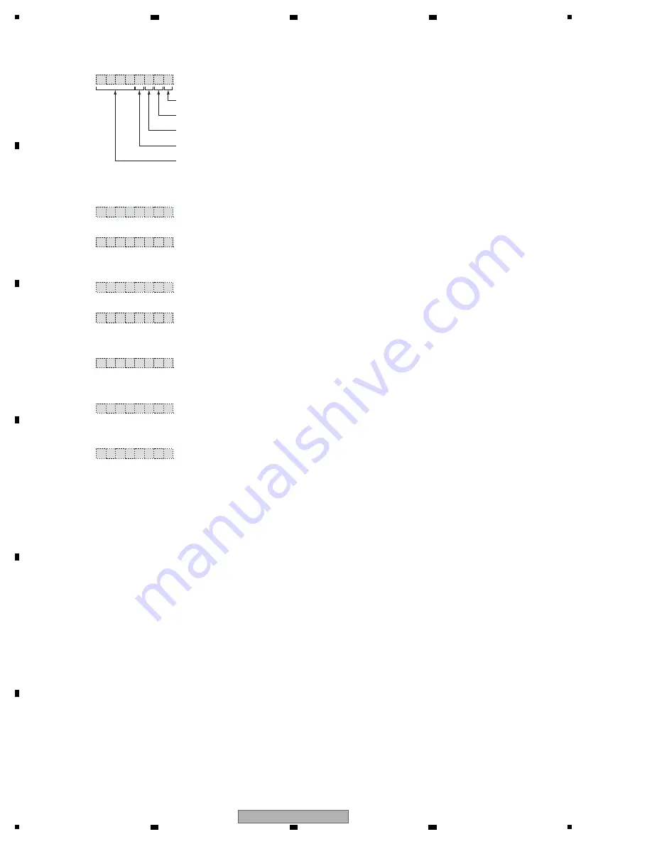
6.7 DISPLAY SPECIFICATIONS OF DSP ERROR
Press "SOUND" button in service test mode to show DSP error message displays.
Press "SOUND" again to select normal service test mode.
This means that the usual function of "SOUND" is not effective in the service test mode.
_ _ _ _
- U M 9
[FL display]
- U M
R
E
I
D
ERR.0
Cannot receive data from the DIR
--> Probably due to faulty DIR or bad connection
- U M
R
E
S
D
ERR.1
Cannot receive data from the DSP
--> Faulty communication between DIR and DSP
--> Probably due to faulty DSP or connection on the circuit board
- U M
Q
E
R
H
ERR.2
No HREQ return value
--> Probably due to faulty DSP
- U M
G
N
S
D
ERR.3
DSP error message
--> Faulty communication between the DIR and DSP
--> Probably due to faulty DSP
-
M
T
U
M
D
ERR.4
DECMUTE on all the time
--> Faulty communication between the DIR and DSP
--> Probably due to faulty DSP
-
9
K
O
S
D
NO ERR
(the source is 88.2/96 kHz.)
96 kHz source play
-
K
O
S
D
NO ERR
(the source is not 88.2/96 kHz.)
No abnormality
[Example]
9
6k (This character is displayed while the source is 88.2 or 96 kHz PCM)
DSP
M
UTE (This character is displayed while DSPMUTE is active)
DIR
U
NLOCK (This character is displayed while DIR is UNLOCK)
Space
The name of an error is displayed by four characters.
DSP error message mode
Содержание XV-DV575
Страница 18: ...18 XV DV575 1 2 3 4 A B C D E F 1 2 3 4 4 3 DVD LOADER DECODER BLOCK DIAGRAM ...
Страница 70: ...70 XV DV575 1 2 3 4 A B C D E F 1 2 3 4 10 11 POWER SUPPLY UNIT AC IN F CN1 ...
Страница 71: ...71 XV DV575 5 6 7 8 5 6 7 8 A B C D E F CN3201 B 4 5 CN1001 B 1 5 F F POWER SUPPLY UNIT XWR3018 CN2 CN3 ...
Страница 85: ...85 XV DV575 5 6 7 8 5 6 7 8 A B C D E F SIDE B SIDE B POWER SUPPLY UNIT F F CN3 ...


