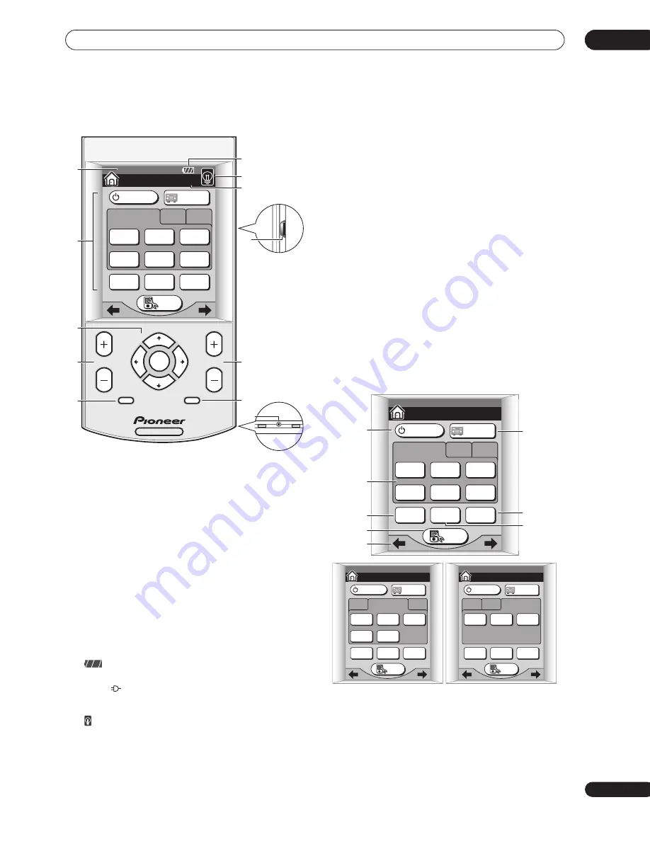
Controls and displays
03
31
En
Remote control
1
Date and time display
See
Setting the clock
on page 9 to set this to the current
time.
2
LCD touch screen
The LCD touch screen appears when the screen is
touched or a button on the remote control is pressed.
3
Cursor hard keys and ENTER
Use to navigate menus and select options/execute
commands.
4
CHANNEL +/–
Use to select channels.
5
MENU / SYSTEM SETUP
Use to display the System Setup menu (or a menu when
controlling other components, such as a DVD or TV).
6
Displays the rechargeable battery status. The recharge
indicator (
) shows when the remote is being
recharged.
7
Press to switch the touch screen backlight on or off.
8
Menu screen number
Displays the screen number in the current menu, as well
as the number of screens.
9
Contrast control
Use to adjust the contrast of the LCD touch screen.
10 /–
Use to adjust the volume.
11 MUTE
Press to mute all output. Press again (or adjust the
volume using the
MASTER VOLUME
control) to restore
the sound.
12 Servicing terminal
For use by Pioneer service technicians.
Basic remote control displays
The remote control LCD touch screen has a number of
displays from which you can control receiver functions,
as well as control operations for other components. The
basic menu screens are explained here.
Home menu screens
There are three Home menu screens, which can be
navigated by using the touch panel
/
(cursor left/
right) soft keys or
INPUT 1
,
2
or
3
.
1
RECEIVER
Press to switch the receiver on or into standby.
RECEIVER
ENTER
CHANNEL
MENU
MUTE
SYSTEM
SETUP
VOLUME
HOME 1/3
07/24 PM 3: 55
SYSTEM
OFF
TV
CONT
MULTI
OPERATION
TV
/ DVD
DVD
/ LD
DVR
/ VCR1
SAT
INPUT 1
2
3
CD
TUNER
SETUP
RECEIVER
RECEIVER
C
ONTRAST
–
+
12
9
1
6
2
7
10
11
3
5
4
8
HOME
SYSTEM
OFF
TV
CONT
MULTI
OPERATION
TV
/ DVD
DVD
/ LD
DVR
/ VCR1
SAT
INPUT 1
2
3
CD
TUNER
SETUP
RECEIVER
RECEIVER
1/3
1
6
2
7
8
3
5
4
HOME
SYSTEM
OFF
TV
CONT
MULTI
OPERATION
MULTI CH
INPUT
CD-R
/ TAPE1
VCR2
VIDEO
VCR3
INPUT 2
1
3
SETUP
RECEIVER
RECEIVER
2/3
HOME
SYSTEM
OFF
TV
CONT
MULTI
OPERATION
i.LINK
USB
PHONO
INPUT 3
1
2
SETUP
RECEIVER
RECEIVER
3/3


