background image


PRS-D1000M/XU/UC

3

5

6

7

8

5

6

7

8

C

D

F

A

B

E

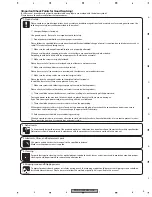
[Important Check Points for Good Servicing]

In this manual, procedures that must be performed during repairs are marked with the below symbol.
Please be sure to confirm and follow these procedures.

1. Product safety

Please conform to product regulations (such as safety and radiation regulations), and maintain a safe servicing environment by 
following the safety instructions described in this manual.

1

  Use specified parts for repair.

Use genuine parts.  Be sure to use important parts for safety.

2

  Do not perform modifications without proper instructions.

Please follow the specified safety methods when modification(addition/change of parts)  is required due to interferences such as 
radio/TV interference and foreign noise.

3

  Make sure the soldering of repaired locations is properly performed.

When you solder while repairing, please be sure that there are no cold solder and other debris.
Soldering should be finished with the proper quantity. (Refer to the example)

4

  Make sure the screws are tightly fastened.

Please be sure that all screws are fastened, and that there are no loose screws.

5

  Make sure each connectors are correctly inserted.

Please be sure that all connectors are inserted, and that there are no imperfect insertion.

6

  Make sure the wiring cables are set to their original state.

Please replace the wiring and cables to the original state after repairs.
In addition, be sure that there are no pinched wires, etc.

7

  Make sure screws and soldering scraps do not remain inside the product.

Please check that neither solder debris nor screws remain inside the product.

8

  There should be no semi-broken wires, scratches, melting, etc. on the coating of the power cord.

Damaged power cords may lead to fire accidents, so please be sure that there are no damages.
If you find a damaged power cord, please exchange it with a suitable one.

9

  There should be no spark traces or similar marks on the power plug.

When spark traces or similar marks are found on the power supply plug, please check the connection and advise on secure 
connections and suitable usage.   Please exchange the power cord if necessary.

0

  Safe environment should be secured during servicing.

When you perform repairs, please pay attention to static electricity, furniture, household articles, etc. in order to prevent injuries.  
Please pay attention to your surroundings and repair safely. 

2. Adjustments

To keep the original performance of the products, optimum adjustments and confirmation of characteristics within specification.
Adjustments should be performed in accordance with the procedures/instructions described in this manual.

4. Cleaning

For parts that require cleaning, such as optical pickups, tape deck heads, lenses and mirrors used in projection monitors, proper 
cleaning should be performed to restore their performances.

3. Lubricants, Glues, and Replacement parts

Use grease and adhesives that are equal to the specified substance. 
Make sure the proper amount is applied.

5. Shipping mode and Shipping screws

To protect products from damages or failures during transit, the shipping mode should be set or the shipping screws should be 
installed before shipment.  Please be sure to follow this method especially if it is specified in this manual.

Содержание PRS-D1000M

Страница 1: ...R EUROPE NV Haven 1087 Keetberglaan 1 9120 Melsele Belgium PIONEER ELECTRONICS ASIACENTRE PTE LTD 253 Alexandra Road 04 01 Singapore 159936 PIONEER CORPORATION 2006 PRS D1000M XU UC CRT3663 CLASS D MONO AMPLIFIER PRS D1000M XU UC PRS D1000M XU EW5 PRS D1000M XU ES For details refer to Important Check Points for Good Servicing K ZZA MAY 2006 Printed in Japan ...

Страница 2: ... known to the state of California to cause cancer birth defects or other reproductive harm Health Safety Code Section 25249 6 Proposition 65 Service Precaution You should conform to the regulations governing the product safety radio and noise and other regulations and should keep the safety during servicing by following the safety instructions described in this manual Be careful in handling ICs So...

Страница 3: ...ide the product Please check that neither solder debris nor screws remain inside the product 8 There should be no semi broken wires scratches melting etc on the coating of the power cord Damaged power cords may lead to fire accidents so please be sure that there are no damages If you find a damaged power cord please exchange it with a suitable one 9 There should be no spark traces or similar marks...

Страница 4: ...CHEMATIC DIAGRAM 10 3 1 SCHEMATIC DIAGRAM GUIDE PAGE 10 3 2 REMOTE CONTROL UNIT 16 4 PCB CONNECTION DIAGRAM 18 4 1 AMP PCB 18 4 2 CONTROL PCB 22 4 3 LED PCB 24 4 4 REMOTE CONTROL UNIT 25 5 ELECTRICAL PARTS LIST 26 6 ADJUSTMENT 32 6 1 OFFSET VOLTAGE ADJUSTMENT 32 7 GENERAL INFORMATION 33 7 1 DIAGNOSIS 33 7 1 1 DISASSEMBLY 33 7 1 2 CONNECTOR FUNCTION DESCRIPTION 34 8 OPERATIONS 35 ...

Страница 5: ...PRS D1000M XU UC 5 5 6 7 8 5 6 7 8 C D F A B E 1 SPECIFICATIONS ...

Страница 6: ...e component parts indicates the importance of the safety factor of the part Therefore when replacing be sure to use parts of identical designation Screw adjacent to mark on the product are used for disassembly For the applying amount of lubricants or glue follow the instructions in this manual In the case of no amount instructions apply as you think it appropriate 17 6 16 11 7 14 4 5 2 10 1 4 3 15...

Страница 7: ...ethylene Bag CEG1171 10 Cord Assy YDE5010 11 Polyethylene Bag See Contrast table 2 12 Carton See Contrast table 2 13 Contain Box See Contrast table 2 14 Protector YHP5006 15 Protector YHP5007 16 Protector YHP5012 17 Protector YHP5013 18 Shaft YLP5001 Mark No Description Part No Mark No Description PRS D1000M XU UC PRS D1000M XU EW5 PRS D1000M XU ES 7 1 Owner s Manual CRD4120 CRD4119 CRD4121 7 2 Ow...

Страница 8: ...R A A D A B C 53 47 47 6 56 5 42 40 43 41 55 44 8 9 8 8 33 32 8 34 8 11 10 27 28 8 53 1 54 3 3 4 4 4 4 4 4 4 4 4 49 4 2 2 12 16 7 12 50 51 52 2 2 9 9 9 18 58 21 17 22 23 25 24 13 57 36 36 46 45 45 46 46 48 46 9 26 35 15 14 38 29 30 31 8 37 37 39 19 20 GYA 009 ...

Страница 9: ...905 VNF1084 26 Cord Assy CN801 YDE5017 27 Terminal CN305 YKE5001 28 Terminal CN306 YKE5001 29 Terminal CN906 YKE5002 30 Fuse Holder CN903 YKR5001 31 Fuse Holder CN904 YKR5001 32 Connector CN101 YKS5008 33 Connector CN103 YKS5009 34 Connector CN902 YKS5010 35 Holder YND5002 36 Insulator YNM5045 37 Cushion YNN5001 38 Sub Heat Sink CNR1883 39 Spacer YNS5118 40 Remote Control Assy CXC4064 41 Cover CNS...

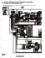
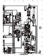
Страница 10: ... b A a Large size SCH diagram Guide page Detailed page Note When ordering service parts be sure to refer to EXPLODED VIEWS AND PARTS LIST or ELECTRICAL PARTS LIST A a A B B CONTROL PCB D CN1351 220 µH 220 µH 20K E 10K A BB ON GAIN TYP 3 8 dBs RCA IN 50 Hz 400 mVrms to 6 5 Vrms 5 74 dBs to 18 5 dBs 3 8 dBs 4 0 dBs 4 1 dBs 4 1 dBs 7 9 dBs ...

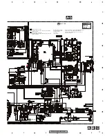
Страница 11: ...R022 The mark found on some component parts indicates the importance of the safety factor of the part Therefore when replacing be sure to use parts of identical designation Symbol indicates a resistor No differentiation is made between chip resistors and discrete resistors NOTE Symbol indicates a capacitor No differentiation is made between chip capacitors and discrete capacitors 10K B 4 1 dBs 7 9...

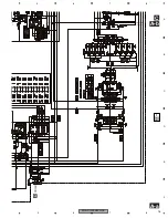
Страница 12: ...0 022 R022 The mark found on some component parts indicates the importance of the safety factor of the part Therefore when replacing be sure to use parts of identical designation Symbol indicates a resistor No differentiation is made between chip resistors and discrete resistors NOTE Symbol indicates a capacitor No differentiation is made between chip capacitors and discrete capacitors 10K B 7 9 d...

Страница 13: ...PRS D1000M XU UC 13 5 6 7 8 5 6 7 8 C D F A B E A a A b A b C 5 6 7 LED PCB C 50 µH ...

Страница 14: ... 14 1 2 3 4 1 2 3 4 C D F A B E A a A b A a A a A b A a B B 1 2 3 4 B CONTROL PCB 20K E 10K A BB ON GAIN TYP 3 8 dBs RCA IN 50 Hz 400 mVrms to 6 5 Vrms 5 74 dBs to 18 5 dBs 3 8 dBs 4 0 dBs 4 1 dBs 4 1 dBs 7 9 dBs 7 9 d ...

Страница 15: ...PRS D1000M XU UC 15 5 6 7 8 5 6 7 8 C D F A B E A a A b A a A b A a C 5 6 7 D CN1351 220 µH 220 µH ...

Страница 16: ...PRS D1000M XU UC 16 1 2 3 4 1 2 3 4 C D F A B E 3 2 REMOTE CONTROL UNIT D A CN241 BASS BOOST D REMOTE CONTROL UNIT ...

Страница 17: ...PRS D1000M XU UC 17 5 6 7 8 5 6 7 8 C D F A B E ...

Страница 18: ...The parts mounted on this PCB include all necessary parts for several destination For further information for respective destinations be sure to check with the schematic dia gram 2 Viewpoint of PCB diagrams 10 20 30 40 50 60 70 80 90 100 110 120 130 140 150 1 X 190 180 170 160 150 140 130 120 110 100 90 80 70 60 50 40 30 20 10 0 Y FRONT FUSE BFC FUSE SPEA POWER TERMINAL 1 1 ...

Страница 19: ...PRS D1000M XU UC 19 5 6 7 8 5 6 7 8 C D F A B E A SIDE A 40 150 170 180 190 200 210 220 230 240 250 260 270 280 290 160 B CN101 RCA SPEAKER OUTPUT SPEAKER OUTPUT 5 2 1 6 7 4 3 8 D CN1351 1 ...

Страница 20: ...PRS D1000M XU UC 20 1 2 3 4 1 2 3 4 C D F A B E A A AMP PCB 140 150 170 180 190 200 210 220 230 240 250 260 270 280 290 160 1 2 1 ...

Страница 21: ...PRS D1000M XU UC 21 5 6 7 8 5 6 7 8 C D F A B E A SIDE B 10 20 30 40 50 60 70 80 90 100 110 120 130 140 150 X 190 180 170 160 150 140 130 120 110 100 90 80 70 60 50 40 30 20 10 0 Y C CN801 1 2 1 ...

Страница 22: ...PRS D1000M XU UC 22 1 2 3 4 1 2 3 4 C D F A B E 4 2 CONTROL PCB B B CONTROL PCB B CONTROL PCB A CN103 POWER MODE INPUT ...

Страница 23: ...PRS D1000M XU UC 23 5 6 7 8 5 6 7 8 C D F A B E B SIDE A SIDE B SUBSONIC MODE SELECT ...

Страница 24: ...PRS D1000M XU UC 24 1 2 3 4 1 2 3 4 C D F A B E 4 3 LED PCB C C LED PCB C LED PCB SIDE A SIDE B A CN902 ...

Страница 25: ...PRS D1000M XU UC 25 5 6 7 8 5 6 7 8 C D F A B E 4 4 REMOTE CONTROL UNIT D D REMOTE CONTROL UNIT D REMOTE CONTROL UNIT SIDE A SIDE B 5 4 3 2 1 1 3 2 4 BASS BOOST 12dB 9dB 6dB 0dB A CN241 1 ...

Страница 26: ... Transistor DTC124EK Q 304 A 272 131 Transistor DTA124EK Q 305 A 208 127 Transistor 2SC4730 Q 306 A 208 133 Transistor 2SA1826 Q 307 A 285 133 Transistor 2SC4730 Q 308 A 285 127 Transistor 2SA1826 Q 309 A 208 139 Transistor 2SA1826 Q 310 A 285 139 Transistor 2SC4730 Q 311 A 270 149 Transistor 2SC1845 Q 312 A 270 140 Transistor 2SC1845 Q 313 A 183 143 Transistor 2SA992 Q 314 A 183 152 Transistor 2S...

Страница 27: ...VH D 910 B 287 64 Diode DAN202U D 911 A 98 58 Diode ERA15 02VH D 912 A 68 59 Diode RM4Z LFJ4 D 913 B 135 41 Diode UDZS7R5 B ZNR201 B 259 34 Surge Protector CSA30 201N ZNR202 B 265 34 Surge Protector CSA30 201N ZNR203 B 256 34 Surge Protector CSA30 201N ZNR204 B 245 34 Surge Protector CSA30 201N L 201 A 285 56 Ferri Inductor CTF1007 Circuit Symbol and No Part No L 202 A 289 56 Ferri Inductor CTF100...

Страница 28: ...10 160 RS1 16S121J R 336 A 215 171 RD1 4PU272J R 337 A 171 178 RS1 2PMF100J Circuit Symbol and No Part No R 338 A 188 178 RS1 2PMF100J R 339 A 193 178 RS1 2PMF100J R 340 A 210 178 RS1 2PMF100J R 341 A 223 178 RS1 2PMF100J R 342 A 248 178 RS1 2PMF100J R 343 A 261 178 RS1 2PMF100J R 344 A 265 178 RS1 2PMF100J R 345 A 268 171 RD1 4PU272J R 346 B 287 153 RS1 16S121J R 347 A 209 160 0 1 Ω CCN1158 R 348...

Страница 29: ... R 948 B 121 49 RS1 16S472J R 949 B 123 49 RS1 16S0R0J R 950 B 125 46 RS1 16S104J R 951 B 115 49 RS1 16S682J R 952 B 103 52 RS1 16S682J R 953 B 113 58 RS1 16S103J R 954 B 142 49 RS1 16S683J R 956 B 131 46 RS1 16S222J R 957 B 128 47 RS1 16S472J R 958 B 136 44 RS1 16S103J R 959 B 134 44 RS1 16S103J Circuit Symbol and No Part No R 960 B 129 43 RS1 16S473J R 961 A 128 39 RD1 4PU222J R 962 A 23 97 RD1 ...

Страница 30: ...339 A 196 158 100 µF 100 V CEHAZL101M2A P45 C 340 A 244 160 CQMBA561J2A C 341 A 259 136 4 7 µF 250 V CCE1036 Circuit Symbol and No Part No C 342 A 189 57 10 µF 100 V CEAT100M2A C 343 A 199 57 10 µF 100 V CEAT100M2A C 344 A 193 39 CFTNA103J50 C 345 A 170 49 CFTNA103J50 C 346 B 224 48 CKSQYB103K50 C 347 A 170 44 CFTNA103J50 C 348 B 226 48 CKSQYB102K50 C 401 A 187 94 CEANP221M10 C 402 A 159 106 CEAT2...

Страница 31: ...C 933 B 125 43 CKSQYB102K50 C 934 A 90 44 CKSQYB103K50 C 935 B 123 43 CKSQYB103K50 C 936 A 90 42 CKSQYB104K50 C 937 B 120 43 CKSQYB104K50 D Unit Number CWM9848 Unit Name Remote Control Unit MISCELLANEOUS Q 1351 B 21 23 Transistor DTC114EU Q 1352 B 22 6 Transistor DTC114EU D 1351 B 12 25 Diode DAN202U D 1352 B 16 6 Diode DAN202U D 1366 B 21 11 Diode UDZS16 B D 1367 B 29 16 Diode UDZS16 B S 1351 A 6...

Страница 32: ...T AMP PCB SIDE A RCA SPEAKER OUTPUT SPEAKER OUTPUT POWER TERMINAL 5 2 1 6 7 4 3 8 1 mV Meter Rg 1k Rg 1k Connection Diagram Offset Voltage Adjustment No Measurement condition Measurement point Adjustment point Adjustment Method 1 Power on SP OUT VR301 mV Meter 0 15 mV No load no input Rg 1k ...

Страница 33: ... Case 1 1 Fig 1 Fig 2 Removing the Case Fig 1 Removing the Amp Unit Fig 2 Remove the two screws Remove the five screws and then remove the Case Disconnect the connector Remove the six screws Remove the nine screws and then remove the Amp Unit 2 2 3 2 2 2 3 2 2 2 3 3 3 3 3 2 2 2 2 3 3 3 2 1 1 1 Amp Unit ...

Страница 34: ...PRS D1000M XU UC 34 1 2 3 4 1 2 3 4 C D F A B E 7 1 2 CONNECTOR FUNCTION DESCRIPTION ...

Страница 35: ...PRS D1000M XU UC 35 5 6 7 8 5 6 7 8 C D F A B E 8 OPERATIONS ...

Страница 36: ...PRS D1000M XU UC 36 1 2 3 4 1 2 3 4 C D F A B E ...

Страница 37: ...PRS D1000M XU UC 37 5 6 7 8 5 6 7 8 C D F A B E ...

Страница 38: ...PRS D1000M XU UC 38 1 2 3 4 1 2 3 4 C D F A B E Grease List Name Silicon Grease Jig No GYA 009 Remarks Between Power TR and Sub Heat Sink ...

Отзывы: