81
PDR-W839
POWER ON
Each mechanism SW is checked.
MECHA SW
• SELINIT SW
(pin 4)
• SEL SW
(pin 5)
• OPEN SW
(pin 90)
• CLOSE SW
(pin 91)
• CLAMP SW
(pin 6)
• HOME SW
(pin 7)
Mechanism SW logic
at HOME position
at CLAMP position
• SELINIT SW
"L"
"L"(clamp tray1) /"H"(clamp tray2,3)
• SEL SW
"L"
"L"
• OPEN SW
"H"
"H"
• CLOSE SW
"L"
"L"
• CLAMP SW
"H"
"L"
• HOME SW
"L"
"L"
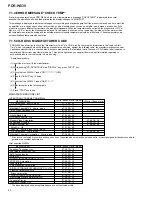
Initialization Sequence at POWER ON of 3CD MICRO CHANGER MECHANISM
Setting the initial condition for shipping
Setting the initial operating condition
The factory default settings shall be as below.
For reason that this product memorizes the condition of below items by back-up battery.
Note) All items are reset to the factory default setting when pushing the MENU key about 10 sec.
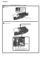
Adjusting the shipping position of mechanism.
Before shipping, it is necessary to adjust the shipping position of the mechanism. See following.
< CD-R tray mechanism >
1. Open CD-R tray and remove a disc.
2. Push OPEN/CLOSE button and wait until the FL display "NO DISC".
< 3CD changer mechanism >
1. Open the tray; CD1–CD3, and remove all discs . And close the tray.
2. Wait until DISC1 to 3 indicators on the FL display, see right, are put out all
and the mechanism is stopped.
3. ON pushing "STOP(CD-R side)" key, and push "PLAY MODE" key .
=
"OK!" is displayed on the FL display, then the mechanism is set to the shipping position.
4. Turn off the power.
Item Initial
condition
REC volume(Analog)
0dB
REC volume(Optical)
0dB
REC volume(Coaxial)
0dB
REC volume FIX(Analog)
ON
REC volume FIX(Optical)
ON
REC volume FIX(Coaxial)
ON
INPUT SELECTOR
ANALOG
MENU
H.P. LEVEL
L
A.TRACK
ON
A.LVL(Analog)
-54dB
A.LVL(Optical)
-54dB
A.LVL(Coaxial)
-54dB
FADER(Analog)
5sec
FADER(Optical)
5sec
FADER(Coaxial)
5sec
T.INC
OFF
BALANCE(Analog)
center
BALANCE(Optical)
center
BALANCE(Coaxial)
center
DISC
DISC
DISC
1
2
3
Содержание PDR-W839
Страница 21: ...PDR W839 21 A B C D 5 6 7 8 5 6 7 8 3 5 A A 1 5 A 2 5 A 4 5 A 1 5 Servo Amp IC Multiplexer ...
Страница 22: ...PDR W839 22 A B C D 1 2 3 4 1 2 3 4 4 5 A EFM ENCODER A 1 5 A 5 5 A 1 5 OP CO 23 24 3 6 CD R CORE ASSY 4 5 ...
Страница 39: ...PDR W839 39 ...
Страница 50: ...PDR W839 50 A B C D 1 2 3 4 1 2 3 4 4 5 MAIN ASSY H MAIN ASSY H CN1201 D CN701 I To POWER SUPPLY ASSY CN1301 L ...
Страница 51: ...PDR W839 51 A B C D 5 6 7 8 5 6 7 8 H PNP1480 C SIDE A CN502 A 301 CN302 A ...
Страница 53: ...PDR W839 53 A B C D 5 6 7 8 5 6 7 8 H IC601 Q492 Q401 Q428 IC1811 IC901 Q490 Q481 1 SIDE B ...
Страница 55: ...PDR W839 55 A B C D 5 6 7 8 5 6 7 8 I L HEAD PHONE ASSY L OPERATING1 ASSY I CN801 H CN901 H To Key Board ...
Страница 56: ...PDR W839 56 A B C D 1 2 3 4 1 2 3 4 I L HEAD PHONE ASSY L OPERATING1 ASSY I IC701 Q708 ...
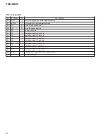
Страница 94: ...94 PDR W839 Pin Function 1 5 PDC069 CD R CORE ASSY IC501 Encoder IC ...
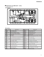
Страница 95: ...95 PDR W839 Pin Function 2 5 ...
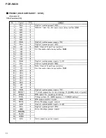
Страница 96: ...96 PDR W839 Pin Function 3 5 ...
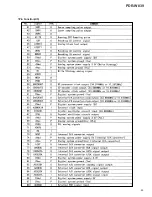
Страница 97: ...97 PDR W839 Pin Function 4 5 ...
Страница 98: ...98 PDR W839 Pin Function 5 5 ...
Страница 103: ...103 PDR W839 ...

